


Jiangsu Acrel Electrical Manufacturing Co., LTD.
News
- Good News! Congratulations to Acrel ADL3000-E Energy Meter for Obtaining The 1st Certificate of UL61010-2-030 Standard in China!1.What is UL certification? UL certification is a safety certification service provided by Underwriters Laboratories Inc. Although UL certification is not mandatory, it is a guarantee for entering the North American market. Products with the UL mark have high market recognition. Acrel ADL3000-E energy meter meets the requirements of UL61010-1, UL61010-2-030, UL61010-2-201 standards, it is worth mentioning that this certificate is the first certificate issued by UL Laboratory in China that industrial meters comply with the UL61010-2-030 standard, and for this reason, UL China held a special ceremony for the issuance of certificates for our company. 2.Acrel DIN-Rail AC Energy Meter ADL3000-E Acrel DIN-rail AC energy meter ADL3000-E, has passed UL certification (Certification No. 2023-01-20-E527278). ADL3000-E is a multi-functional smart meter designed for power supply systems, industrial and mining enterprises and public utilities for calculating electricity consumption and managing power demand. It integrates the measurement of common electrical parameters with comprehensive power metering and management, and provides 12 months of various power statistics. It has the function of detecting the 2nd~31st sub-harmonics and total harmonic content, with switching input function. It has RS485 communication port, MODBUS-RTU or DL/T645 protocol can be selected. This energy meter can be widely used in various control systems, SCADA systems and energy management systems. 3.Function Three-phase electrical parameters U, I, P, Q, S, PF, F measurement; Forward and reverse active power measurement, forward and reverse reactive power measurement; Measurement of 2nd~31st sub-harmonics and total harmonic content; Active power precision 0.5S Class, reactive power precision 2 Class; Display: 8-bit segment code type liquid crystal screen (LCD); Communication interface: RS485, infrared; Communication protocol: Modbus-RTU, DL/T 645-2007; Pulse output: 1 channel active power pulse output; Switching function: 1 channel switching input. 4.The Site Application Photo of ADL3000-E
2023 10/09
- Application of precision power distribution multi-circuit monitoring devices in railway transportation projectsEngineer:Lukas Lu Tel:+86 18761593924 E-mail:lukas.lu@email.acrel.cn Jiangsu Acrel Electrical MFG Co. Ltd Abstract:As a part of the urban public transportation system, ailway transportation has been extensively developed and expanded in the past few decades. It plays an important role in solving urban traffic congestion, reducing environmental pollution, and improving urban sustainability. With the advancement of science and technology, ailway transportation systems are constantly introducing new technologies and innovations to improve operating efficiency and passenger experience, save energy and reduce operating costs. The monitoring of air-conditioning circuits in rail transit train carriages is one of the important aspects to ensure the comfort and safety of passengers in the train. Monitor the electrical parameters of the air conditioning circuit in real time to determine the operating status of the air conditioner, detect potential faults, and take timely measures when power problems occur to ensure the operation of the air conditioning system. At the same time, monitoring data of the air conditioning loop should be recorded for subsequent analysis and trend observation, which can help identify the long-term performance and health of the system. Keywords:Precision distribution,multi circuits monitoring,railway transportation,leakage current 1.The specific requirements of air-conditioner circuits on rail transit train are as follows: 1.1.The train continues to vibrate during operation, so there are higher requirements for the seismic resistance of the monitoring module. The module terminals need to be tightened with screws and pass environmental tests, shock and vibration tests and other related tests; 1.2.Trains have a large passenger flow and are densely packed with passenger. Most of the seats, ceilings and other decorative materials are flammable. Once a fire breaks out, it can easily cause safety hazards. For safety reasons, the modules need to pass relevant tests such as fire protection and flame tests; 1.3.The module is installed on the mounting plate on the top of each carriage. The installation space is limited, so the module needs to be small, thin and mounted on guide rails; 1.4.It is necessary to monitor the residual current of the 4-channel air-conditioner incoming circuits and the 8-channel air-conditioning load current. 2.Product details Acrel AMC16Z-FAL multi-channel current monitoring device has a compact design and can meet the real-time collection and monitoring of a total of 24 currents and 4 residual currents on sides A and B. It achieves the height of a monitoring loop in the size of a traditional instrument. The device has EN45545-HL3 fire protection report, ISO1716 flame test report, EN50155 type test report, EN50155 type test report, TB/T3139-2021 prohibited and restricted substances report, accuracy and calibration measurement report. Model AMC16Z-FAL Measurement Current,leakage current Load Current Rated current 50mA Range 0.125~60mA Overload Continuous 1.2 times, instantaneous 10 times/second Accuracy 0.5class Leakage current Range 300-1000mA Accuracy 1class Power supply DC12-24V Environment Tmep Woring:-15℃~55℃ Storage:-25℃~70℃ Humidity Relative humidity≤93% Attitude ≤2500m Communiction RS485/Modbus-RTU Installation way Din Rail 35mm Protection Level IP20 Pollution Level 2 2.1.Dimension 2.2.Installation AMC16Z-FAL module is installed on the top of each carriage to measure the residual current and load current. All the data are transmitted to the data collection terminal at the front of the train through RS485 communication. After arriving at the station, the staffs remove the data collection terminal and summarize the data to the comprehensive monitoring platform. Through real-time monitoring of these electrical parameters of the air-conditioning power distribution circuit, the operating status of the air-conditioning can be judged, potential faults can be detected, and effective measures can be taken promptly when power problems occur. Make sure the air conditioning system is functioning. 2.3.Site Photos 3.Conclusion: Urban transportation Rail transit is a safe and environmentally friendly way. With the acceleration of urbanization and the growth of urban population, rail transit has developed rapidly in many countries and regions. Acrel independently developed a precision standby multi-circuit monitoring device to monitor the current and residual current of the air-conditioning wiring circuit in the subway train compartment, evaluate the energy consumption of the air-conditioning system through the air-conditioning operating status data, and further optimize the design and operation of the system. Saving energy and reducing operating costs, while ensuring normal operation, troubleshooting equipment failures in a timely manner, and providing passengers with a safe and comfortable riding environment are a very important part of subway operations. References: [1] Acrel Enterprise Microgrid Design and Application Manual. Version 2022.05
2023 09/27
- Application and product selection of electric power monitoring system in intelligent buildingEngineer: Ella Wong Tel: +86 18761596287 E-mail:ella.wong@email.acrel.cn Jiangsu Acrel Electrical MFG Co. Ltd Abstract: In recent decades, China's modern economy has continued to develop, and computer technology, information technology and other related industries have also made rapid progress.As commercial, residential and public buildings continue to increase their requirements for intelligent management and energy conservation, power monitoring systems have begun to gradually penetrate into people's daily lives and play an irreplaceable role.The optimization of the economic atmosphere has generally increased people's demands for the reliability, safety, comfort, and efficiency of office and living environments. Intelligent buildings have emerged as the times require, successfully achieving the perfect combination of quality of life and information services, and becoming the construction industry of the 21st century. mainstream.Intelligent buildings are not only the embodiment of the country's comprehensive national strength and technological level, but also reflect the social development's concern for human nature. Keyword: electric power monitoring, intelligence,monitoring system 1.Features of Intelligent buildings Intelligent buildings are modern achievements that combine cultural landscapes with ecological nature.Aiming to provide people with a safe, reliable, comfortable and natural living environment and an active and healthy lifestyle.It integrates the data communication, voice communication and multimedia communication of the whole building or the whole community to form a communication network with a wide range and rich content.Such a modern communication method effectively meets the efficient and fast-paced work needs of modern information society.An electronic monitoring system provides an intelligent system platform for unified monitoring and management of high and low voltage power distribution, information exchange, and resource sharing in the building. 2.Overview of power monitoring system The power monitoring system uses modern network technology and computer video technology to monitor the operating parameters, event records, wave records and other data of the power system.At the same time, it is continuously transmitted to the power monitoring computer and implemented remote control commands, so that operation managers can fully understand the operating status of the power system through the monitoring center.Therefore, the location and cause of the fault can be accurately and quickly judged, the work process is simplified, and the staff can provide a limited way to solve the problem in a targeted manner. 3.Application of Power Monitoring System in Intelligent Building Power monitoring systems are widely used in smart buildings.Solar energy, solar greenhouse, water ring heat pump air conditioning technology, and ground source heat pump cavity technology are all its manifestations.The secondary equipment in the power distribution room (safety automatic device, traditional measuring instrument, operation control, signal system) is a power monitoring system involving lighting, power distribution, heating, communication, alarm and other aspects, which is widely used in intelligent buildings.Related systems communicate with smart devices,Including: building equipment automation system, communication network system, office automation system, automatic fire alarm system to achieve mutual communication and information sharing between automation systems.Benefits brought by electronic monitoring systems: The solar panels in the sun room collect heat extensively and transmit it to the automatic display system. At the same time, the automatic power generation system transmits the generated electricity to every corner of the home through energy conversion.Effectively utilize renewable resources, cut costs, reduce failures, and maximize the benefits of effective resources;Solar greenhouses minimize the disadvantages of plants affected by seasons, and the most efficient photosynthesis optimizes fruits to the greatest extent.Systematization, environmental protection, standardization and efficiency are necessary conditions for future circular and sustainable economic development, and have become the only choice to promote economic development in the information age. 4.The role of power monitoring system in intelligent building Due to the development of new system technologies such as network technology, video technology, communication technology, and intelligent power distribution, and the application of power monitoring systems in intelligent buildings,The future intelligent building is developing in the direction of intensification, systematization and standardization.Reliable, safe, convenient and simple way of life enables people to enjoy a higher degree of green life. The value generated by the power monitoring system in intelligent buildings: According to survey data: Every year, electronic monitoring systems in various related enterprises, institutions and public places spend huge amounts of money on maintenance and configuration.Moreover, there is a lot of power loss, which not only causes a waste of resources but also affects the normal life of residents.Here are two examples: Case 1:Recently, a very serious transient failure occurred inside an important piece of equipment of a well-known computer manufacturing company.But it quickly returned to normal. Without a monitoring system, this failure could not be detected at all.This is a terrible potential threat, because the installed electronic monitoring system discovered this fault in time and captured and recorded the transient fault waveform.This information saved DELL company 25,000 yuan in equipment maintenance costs. Case 2:In February 2013, the lead clip from bus No. 1 to Jingzao of a 220kV substation of a thermal power plant broke. When the lead wire fell, it touched the No. 2 busbar, causing the whole station to lose voltage, and the Jingzao line was cut off.The line tripped, causing Hubei Jingmen Power Supply Company's Zaoshan substation and five 110kV substations to stop.The accident caused a load loss of 90,000 kW, accounting for 10.8% of Jingmen City's total load, and affected 63,000 users, accounting for 6.7% of the city's users. caused huge losses. In order to solve this problem, the application of intelligent buildings is making intelligent buildings develop in the direction of intensification, systematization and standardization.The application of electronic monitoring systems reduces the waste of equipment operation and power consumption; it rationally and effectively utilizes the maximum advantages of the equipment, reduces unnecessary purchases, avoids waste of resources, and saves a lot of money;Potential faults are discovered in time, reducing equipment maintenance costs, not only extending the service life of the equipment, but also achieving maximum utilization of resources; Improved operation management efficiency and reduced the workload of operation and maintenance personnel,At the same time, it also improves the stability and reliability of power, shortens power outage time, reduces fires, avoids accidents, and ensures the safety of people's lives and property.Users can also enjoy a more intelligent, green and environmentally friendly life. 5. Energy saving and prospect optimization analysis of intelligent buildings Intelligent buildings have become the mainstream in the construction industry in the 21st century,With the development of the economy and the theoretical requirements of sustainable development, the energy saving of intelligent buildings must follow the efficient economic model of low energy consumption, low input and high output.Let the circular economy not only exist in innovative energy-saving companies that master the latest technology, but also penetrate into every corner of life.The main feature of smart buildings is resource efficiency.While building buildings that are more comfortable and more in line with modern requirements, owners take green energy conservation as their starting point and goal in order to save high expenses.Sustainable building designs with the lowest energy consumption and operating costs generally include the following technical measures: ①Energy saving.②Reduce the development of limited resources and increase the development of renewable sources and new energy.③Humanism of interior environment and quality.④Minimize the impact of the site and environment on the implementation and development of the building.⑤New propositions for art and space.⑥Intelligent. Realize the maximum utilization and recycling of resources. In the future, intelligent buildings will pay more attention to the development of human nature and the maximization of environmental benefits.Creating a healthy, comfortable, green, environmentally friendly, simple and convenient living environment and modern quality of life is the common wish of more and more people.It is also the basis and goal of building energy conservation.The future development of smart buildings must achieve the following points: ①Warm in winter and cool in summer, providing people with a comfortable living environment. ②Good ventilation, fresh and smooth breathing. ③Sufficient light, try to use natural light, natural lighting, combined with artificial lighting. ④Intelligent manual control.Ventilation, lighting, heating, home appliances, etc. can all be controlled by computers, which can be managed according to predetermined programs or controlled locally.It meets the different needs of people in different situations, while recycling resources and reducing waste. 6.Optimizing the application prospects of electronic monitoring systems in the future As a unique invention of the information age, the electronic monitoring system plays an irreplaceable role in people's production and life.In recent years, economic development has also brought a series of social problems:Land loss is serious, environmental pollution is intensifying, violent crimes are increasing, social regulation systems are disordered, and natural self-purification and self-rescue capabilities are weakening.Therefore, the power monitoring system will develop from simple monitoring and display to a more automated and intelligent direction.It will realize massive information storage, quickly and directly complete data collection, analysis and processing, and make effective instruction prompts.Make problem solving faster and more accurate.Save more manpower and money, and realize the conservation and efficient use of natural and social resources.At the same time, more new features will be extended: (1)Advancement: Make full use of the latest modern and future technologies to develop the most reliable scientific and technological achievements. (2)Reliability: Become a more mature technology product. Adapt to social development. (3)Practicality and convenience:It is convenient, safe and durable to meet market demand and actual use needs to the greatest extent. (4)Scalability and economy:Enhanced compatibility, continuously optimized design, and improved performance. (5)Normalization and structuring:Due to the realistic characteristics that market information itself is not subject to human subjective will,electronic monitoring systems should be more structured, standardized and serialized. 7.Acrel power monitoring system product introduction and selection 7.1 Overview Acrel IoT power monitoring system is Acrel Electric Co., Ltd. according to the requirements of power system automation and unattended,A set of hierarchical distributed substation monitoring and management systems developed for voltage levels of 35kV and below.The system is based on the application of electric power automation technology, computer technology and information transmission technology,It is an open, networked, unitized and configurable system that integrates protection, monitoring, control, communication and other functions.It is suitable for urban power grid, rural power grid substations and user substations with voltage levels of 35kV and below.It can realize the control and management of the substation orientation and meet the needs of unmanned or less manned substations.It provides a solid guarantee for the safe, stable and economical operation of the substation. 7.2 Application (1)Office building(Business offices, state agency office buildings, etc.) (2)Commercial Building(Shopping malls, financial institution buildings, etc.) (3)Tourist building(Hotels, restaurants, entertainment venues, etc.) (4)Science, education, culture and health buildings(Culture, education, scientific research, medical and health, sports buildings) (5)Communication building(Posts and telecommunications, communications, radio, television, data centers, etc.) (6)Transportation buildings(Airports, stations, wharf buildings, etc.) (7)Factories, mines and enterprise buildings(Petroleum, chemical industry, cement, coal, steel, etc.) (8)New Energy Building(Photovoltaic power generation, wind power generation, etc.) 7.3 System structure Acrel IoT power monitoring system adopts hierarchical distributed design,Can be divided into three layers: Station control management layer, network communication layer and field equipment layer,the networking mode can be standard network structure, optical fiber star network structure, optical fiber ring network structure,According to the user's power consumption scale, distribution of power consumption equipment and floor area, etc, the networking mode is comprehensively considered. 7.4 Equipment selection Application Appearance Type Function 35KV AM6-F Three-stage type (with direction, composite tortoise voltage locking) overcurrent protection, small current grounding selection protection, three-phase one-time reclosing, low-frequency load shedding 35KV (above 2000 kVA) AM6-D2 Two 8B transformers/three picture transformers differential quick-break protection, proportional braking differential protection AM6-D3 AM6-T Transformer backup protection measurement and control, equipped with transformer protection AM6-FD Transformer building non-electrical protection (independent), independent operating circuit 35kV motor (above 2000kW) AM6-MD Motor differential protection, motor comprehensive protection 35kV PT monitoring AM6-U PT monitoring 35kVr AM6-TR Three-stage overcurrent, overload protection, transformer non-electricity protection 10kV/6kV feeder AM5-F Three-stage overcurrent/zero sequence overcurrent, overload protection (alarm/trip), PT disconnection alarm, three-phase one-time reclosing low frequency, post-acceleration overcurrent, reverse power protection 10kV/6kV factory transformer AM5-T Three-stage overcurrent/zero-sequence overcurrent, overload protection (alarm switch), control fault alarm, PT disconnection alarm, non-electrical parameter protection 10kV/6kV asynchronous motor AM5-M Two-stage overcurrent/zero sequence overcurrent/negative sequence overcurrent protection, overload protection (alarm system), low voltage protection, PT disconnection alarm, stall protection, start-up timeout, thermal overload protection 10kV/6kV capacitor AM5-C Two-stage overcurrent/zero sequence overcurrent protection, overload protection (alarm trip), PT disconnection alarm, overvoltage/undervoltage tripping, unbalanced voltage/current protection 10kV/6kV bus coupler AM5-B Incoming line standby switching/bus tie standby switching, two-stage overcurrent protection, PT disconnection alarm 10KV/6KV PT monitoring AM5-U Low voltage warning, PT disconnection warning, over voltage warning, zero sequence over voltage warning, 10kV/6kV PT AM5-BL PT secondary paralleling/de-paralleling control of single bus sectional system Centralized collection equipment for wireless temperature measurement Acrel-2000T/A Wall mounted One standard 485 interface, one Ethernet port Built-in buzzer alarm Cabinet size 480*420*200 (unit mm) Display terminal ATP007/ ATP010 DC24V power supply; one way uplink RS485 interface; one way downlink RS485 interface; Receiver: ATC600-C. ARTM-Pn Surface frame 96*96*17mm, depth 65mm; bore diameter 92*92mm; AC85-265V or DC100-300V power supply; One way uplink RS485 interface, Modbus protocol; Receive 60 pcs ATE100M/200/400; match ATC450. Intelligent temperature inspection instrument ARTM-8 Bore diameter 88*88mm embedded installation; AC85-265V or DC100-300V power supply; One way uplink RS485 interface, Modbus protocol; Can be connected to 8-way PT100 sensors, suitable for temperature measurement of low-voltage switch-gear electrical contacts, transformer windings, click windings, etc.; ARTM-24 35mm din rail installation; AC85-265V or DC100-300V power supply; One way uplink RS485 interface, Modbus protocol; 24 channels of NTC or PT100, 1 channel of temperature and humidity measurement, 2 channels of relay alarm output, used for temperature measurement of low-voltage electrical contacts, transformer windings, click windings and other places; Wireless transceiver ATC600 ATC600 has two specifications: ATC600-C can receive the data of 240 pcs ATE100/ATE100M/ATE200/ATC400/ ATE100P/ATE200P sensor. ATC600-Z does relay transparent transmission. Battery Type Wireless Temperature Sensor ATE100M Battery powered,service life ≥ 5 years; -50°C~+125°C; accuracy ±1°C; 470MHz, open distance 150 meters; 32.4*32.4*16mm (length*width*height) ATE200 Battery powered, service life ≥ 5 years; -50°C~+125°C; accuracy ±1°C; 470MHz, open distance 150 meters; 35*35*17mm, L=330mm (length*width*height, three-color strap). ATE200P Battery powered, service life ≥ 5 years; -50°C~+125°C; accuracy ±1°C; 470MHz, open distance 150 meters, protection class IP68; 35*35*17mm, L=330mm (length*width*height, three-color strap). CT power-taking wireless temperature sensor ATE400 CT induction power supply, starting current ≥5A; -50℃~+125℃; accuracy ±1℃; 470MHz, open distance 150 meters; fixed alloy sheet, power supply; three-color shell; 25.82*20.42*12.8mm (length*width *high). 8.Conclusion Electronic monitoring systems are a product of the information age.It reflects the unremitting pursuit and good hope of human beings for quality of life and simplified work procedures in the era of high-efficiency economy.Its wide application in intelligent buildings promotes the intelligence and simplicity of people's lives, and reflects the social, scientific, technological and economic development's concern for people;The embodiment in life makes people appreciate its safety, reliability and high efficiency.It can be said that the electronic monitoring system benefits every aspect of life. Reliance on electronic systems is increasing day by day. References: [1] Acrel Enterprise Microgrid Design and Application Manual. Version 2022.05
2023 09/27
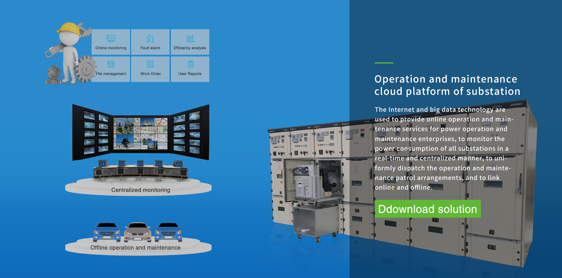
- Analysis and application of unattended substation operation and maintenance cloud platformTina Li Jiangsu Acrel Electrical Manufacturing Co.LTD. Wuxi Jiangsu 214405 Abstract: With the promotion of smart substations, the power system adopts reliable, integrated, and environmentally friendly smart equipment, relying on the digitization of station-wide information, standardization of information sharing, and networking of communication platforms to automatically complete the collection, measurement, protection, and monitoring of substation equipment information. For basic functions such as control, the traditional "visible" and "tangible" secondary circuit has become an "invisible" and "tangible" "black box", which increases the uncontrollability of substation operation, maintenance and maintenance. , this paper proposes a research plan for an intelligent substation operation and maintenance management platform. It can remotely control and control the substation relay protection. Enable remote online monitoring and intelligent operation and maintenance management of operation and maintenance stations and maintenance work areas. Keywords: online monitoring, condition assessment, fault location, auxiliary safety measures, fault analysis 0.Introduction To improve the maintenance level of substation secondary equipment, it is necessary to visualize the equipment, provide multi-dimensional visual information support, decision-making and safe operation for the daily operation and maintenance, abnormality handling, accident analysis and maintenance of substation secondary system, and develop advanced applications based on the operation and maintenance platform to improve the level of equipment refinement management. The substation intelligent operation and maintenance management platform obtains information from the process layer network and station control layer network, highly integrates the information related to operation and maintenance, realizes the applications of visualized online monitoring and intelligent diagnosis, and supports remote uploading. Its main functions include multi-dimensional operation and maintenance management, such as online monitoring, condition assessment and monitoring and warning of secondary equipment, fault localization, auxiliary safety measures for secondary maintenance, configuration file management, protection value management, fault information management and comprehensive analysis. 1.Overview of substation operation and maintenance cloud platform AcrelCloud-1000 substation operation and maintenance cloud platform based on Internet +, big data, mobile communications and other technology development of the cloud management platform, to meet the needs of users or operation and maintenance companies to monitor the operating status and parameters of many substation circuits, indoor environmental temperature and humidity, cable and busbar operating temperature, on-site equipment or environmental video scenes, etc., to achieve a center of the data, centralized storage, unified management, easy to use, to support the user with the right to access through the computer, cell phone, PAD and other types of terminal links, receive alarms, and to complete the relevant equipment, such as daily and regular inspections and dispatches, etc., management. 2.Application It is applicable to the new construction, expansion and reconstruction of power distribution operation and maintenance system in telecommunication, finance, transportation, energy, medical and health care, culture and sports, education and scientific research, agriculture, forestry and water conservancy, commercial services, public utilities, electronic industrial park and other industries. 3.platform structure A set of intelligent gateway is installed in the substation distribution room to collect the data of intelligent equipment in the substation room, and after protocol conversion, compression and encryption, it is uploaded at regular intervals or uploaded to the platform in a triggered manner. The platform can complete the data exchange of all the intelligent equipments in the substation and distribution room, and it can real-time monitor the operation status of transformers, circuit breakers, and other important operating equipments in the substation; it can real-time monitor the operation data of the circuits in the substation and distribution room as well as the digital quantities of the ambient temperatures etc.; and the communication and management unit is connected with the plant's local area network (LAN) and passes the data to the data center. AcrelCloud-1000 substation operation and maintenance cloud platform provides user profiles, power data monitoring, power quality analysis, power consumption analysis, daily, monthly and annual energy consumption data reports, abnormal event alarms and records, operating environment monitoring, equipment maintenance, user reports, Operation and maintenance dispatching and other functions, and supports multi-platform and multi-terminal data access. The AcrelCloud-1000 substation operation and maintenance cloud platform system can be divided into four layers: perception layer, transmission layer, application layer and display layer. Perception layer: includes multi-functional instruments, temperature and humidity monitoring devices, cameras, switching quantity acquisition devices, etc. installed in the substation. In addition to the camera, other devices are connected to the RS485 port of the on-site smart gateway through the RS485 bus. Transport layer: includes on-site intelligent gateways, switches and other equipment. The intelligent gateway actively collects data from on-site device layer devices, performs protocol conversion, data storage, and uploads the data to the designated server port through the switch. When the network fails, the data can be stored locally and resumed from the interrupted location when the network recovers. Upload data to ensure that server-side data is not lost. Application layer: includes application server and database server. If the number of substations is less than 30, the application server and database server can be configured in one. The server needs to have a fixed IP address to receive data actively sent by each smart gateway. Display layer: Users access platform information through multiple terminals such as mobile phones, tablets, computers, etc. 6.platform functions 6.1. Real-time monitoring Click on the power distribution circuit to view detailed power consumption data, generate power operation reports, and query historical data and environmental data monitoring of various power parameters, voltage, current, power, harmonics, etc. 6.2. Monthly energy consumption report The monthly energy consumption report allows users to query the electricity consumption of managed stations based on total electricity consumption, substation name, substation number, etc. The query span can be set to months. 6.3. Site monitoring Site monitoring includes overview, operating status, event records of the day, hourly power consumption curve of the day, and power consumption overview. 6.4. Transformer status Transformer status supports users to query the transformer power, load factor, and other operating status data of all or a certain station, and supports ranking in ascending or descending order by load factor, power. 6.5. Power operation and maintenance Operation and maintenance displays the location and total amount information on the substation map currently managed by the user. 6.6.Power distribution diagram The power distribution diagram displays the power distribution information of the selected substation. The power distribution diagram displays the switching status, current and other operating status and information of each circuit, and supports detailed operating parameter queries such as voltage, current, and power. 6.7.Video surveillance Video surveillance displays the current real-time picture (video live broadcast). By selecting a certain power transformation and distribution station, you can view the video information in the power transformation and distribution station. 6.8. Power operation report The power operation report displays the real-time values and average row statistics of the specified collection interval operating parameters of each circuit of the selected equipment in the selected station and the electric energy meter reading. 6.9. Fault alarm Telemetry, remote signaling alarm (webpage and SMS), upper and lower alarm limits can be set, alarm for substation operating environment (flooding, smoke, etc.) 6.10. Task management The task management page can publish inspection or defect elimination tasks, check the status and completion of inspection or defect elimination tasks, and click View Task to view specific inspection in information 6.11. User Report The user report page is mainly used to automatically summarize a month's operation data of the selected transformer and distribution station, perform statistical analysis on transformer load, distribution circuit power consumption, power factor, alarm events, etc., and list them within that period. Various types of defects discovered during inspections and their treatment. 6.12. Mobile APP The APP supports power operation and maintenance. The mobile APP supports seven modules: "monitoring system", "equipment files", "to-do items", "inspection records", "defect records", "document management" and "user reports". Primary graph, demand, electricity consumption, video, curve, temperature and humidity, year-on-year, month-on-month, power quality, various event alarm inquiries, equipment file inquiries, to-do event processing, inspection record inquiries, user reports, document management, etc. . 7.System hardware configuration Application model image Function Substation operation and maintenance cloud platform AcrelCoud-1000 The platform provides user profiles,power data monitoring, power quality analysis,power consumption analysis,daily, monthly and annual energy consumption data reports,abnormal event alarms and records, operating environment monitoring, equipment maintenance,user reports,operation and maintenance dispatch and other functions,and supports Multi-platform, multi-terminal data access Gateway ANet-2E4SM 4 RS485 serial ports,optocoupler isolation,2 Ethernet interfaces, supporting ModbusRtu,ModbusTCP, DL/T645-1997,DL/T645-2007, CJT188-2004,OPC UA,ModbusTCR(master,slave),104 (master-slave),building energy consumption,SNMP,MQTT;(main module) input power supply: DC 12V~36V.Supports 4G expansion module,485 expansion module. Extension modules ANet-485 M485 module:4-channel optocoupler isolation RS485 Extension modules ANet-M4G M4G module:supports 4G full network communication Medium voltage incoming line AM6-L Three-stage overcurrent protection (with direction,low voltage locking),overload protection,PT disconnection alarm,reverse power protection, three-phase one-time reclosing, low-frequency load shedding, synchronization detection, loop closing protection,circuit breaker failure protection Medium voltage incoming line APM810 Three-phase(I,U,kw,kvar,kwh, kvarh,Hz,cosΦ),zero-sequence current In; four-quadrant electric energy,real-time and demand, current and voltage imbalance load current histogram display;66 alarm types and external events (SOE),16 event records each,supporting SD card expansion recording;2-63 harmonics; 2DI+2D0,RS485/Modbus; LCD display; APView500 Phase voltage and current + zero-sequence voltage and zero-sequence current,voltage and current unbalance,active and reactive power and energy,event alarm and fault recording, harmonics(voltage/current 63 harmonics,63 inter-group harmonics,harmonics Phase angle, harmonic content rate,harmonic power,harmonic distortion rate, K factor),fluctuation/flicker, voltage swell,voltage sag,voltage transient,voltage interruption, 1024-point waveform sampling,triggering and timing recording Wave, waveform real-time display and fault waveform viewing,PODIF format file storage,memory 32G,16D0+22D1, communication 2RS485+1RS232+1GPS, 3 Ethernet interfaces (+1 maintenance network port) + 1USB interface,supports U disk reading data ,supports 61850 protocol. Medium voltage feeder Medium voltage feeder AM6-L Three-stage overcurrent protection (with direction, low voltage locking), overload protection, PT disconnection alarm, reverse power protection, three-phase one-time reclosing, low-frequency load shedding, synchronization detection,loop closing protection,circuit breaker failure protection APM810 Three-phase (I,U,kw,kvar,kwh, kvarh,Hz,cosΦ) zero sequence current In;four-quadrant electric energy;real-time and demand, current and voltage imbalance;load current histogram display;66 alarm types and external events (SOE), 16 event records each,supporting SD card expansion record;2-63rd harmonic;2DI+2D0 RS485/Modbus;LCD display Medium voltage feeder AEM96 Three-phase electrical parameters U,I,P,Q,S,PF,F measurement,total forward and reverse active energy statistics,forward and reverse reactive energy statistics;2-31 sub-harmonic and total harmonic content analysis, Phase-separated harmonics and fundamental wave electrical parameters(voltage,current, power);current specification 3X1.5(6)A, active energy accuracy 0.5S level,reactive energy accuracy level 2;operating temperature:-10C~+55C;Relative humidity:≤95,no condensation Low voltage outlet AEM72 Three-phase electrical parameters U,I,P,Q,S,PF,F measurement,total forward and reverse active energy statistics,forward and reverse reactive energy statistics;2-31 sub-harmonic and total harmonic content analysis,Low-voltage outlet line split-phase harmonics and fundamental wave electrical parameters(voltage,current, power);current specification 3x1.5(6)A,active energy accuracy 0.5S level,reactive energy accuracy level 2 Low voltage outlet ADW300 Three-phase electrical parameters U,I,P,Q,S,PF,F measurement, active energy measurement (forward and reverse),four-quadrant reactive energy,total harmonic content,fractional harmonic content(2nd to 31st);A, B, C, N four-channel temperature measurement,1 channel residual current measurement;supports RS485/LoRa/2G/4G/NB;LCD display; active energy accuracy:0.5S level (recommended for renovation projects) Wireless temperature measurement ATE400 Fixed with alloy sheet,CT induction takes power,starting current is greater than 5A, temperature measurement range -50~125℃,measurement accuracy ±1℃;transmission distance is 150 meters in open space ATC600 Two working modes:terminal and relay.ATC600-Z does relay transparent transmission.The transmission distance from ATC600-Z to ATC600-C is 1000m. ATC600-C can receive data transmitted by ATE series sensors, AHE,etc.,1 channel 485,2 alarm outlets Ambient temperature and humidity WHD WHD temperature and humidity controller products are mainly used for internal temperature and humidity regulation and control of medium and high-voltage switch cabinets, terminal box ring network cabinets, box-type transformers and other equipment. Working power supply AC/DC85~265V, working temperature: -40.0C~99.9C, working humidity 0RH~99RH water immersion sensor RS-SJ-*-2 Contact water immersion sensor, monitors water accumulation in substations, cable trenches, control rooms and other places, working power supply: DC 10-30V, working temperature: -20C+60℃, working humidity: 0%RH~80%RH, response Time: 1s, relay output: normally open contact. camera CS-C5C-3B1WFR Supports 720P high-definition images, with the highest supported resolution up to 1.3 million pixels (1280*960). Built-in microphone and speaker have two-way voice intercom function. Supports EZVIZ Cloud Internet service, enabling remote interaction and video viewing through mobile phones, PCs and other terminals. smoke sensor BRJ-307 Photoelectric smoke sensor: Positive power supply (DC 12V): +12V Relay output: normally open contact access control MC-58(Normally open type) Normally open type, sensing distance: 30-50mm, material: zinc alloy, silver gray electric meter, dry contact output. Matching accessories ARTU-K16 Normally open type, sensing distance: 30-50mm Material: zinc alloy, silver gray electrical dry contact output KDYA-DG30-24K Output DC 24V; 24V power supply 8.Conclusion The application of the intelligent substation operation and maintenance management platform can transform the existing transmission and maintenance modes into remote online diagnosis of actual operating conditions and targeted inspections based on the health status of the equipment, greatly reducing the number of operation and maintenance personnel. Conduct operation, maintenance and inspection frequency of on-site relay protection devices to improve the level of refined management of equipment. The research on remote intelligent operation and maintenance technology of relay protection is of great significance. References [1] Acrel User Substation Comprehensive Automation and Operation and Maintenance Solution. Version 2020.05 [2] Enterprise Microgrid Design and Application Manual. Version 2020.06 [3] Wang Yan, Research on intelligent substation operation and maintenance technology [J]. Communications World, 2015 (22). [4] Zhang Zhiqiang, Research on intelligent operation and maintenance management platform for substations.
2023 09/26
- Centralized monitoring system solution for wind farmsEngineer: Besty Chen Tel: +86 18761509710 E-mail: besty.chen@email.acrel.cn Jiangsu Acrel Electrical MFG Co. Ltd Abstract: As one of the clean energy sources, the installed capacity of wind farms has grown rapidly in recent years. Wind farms are divided into onshore wind farms and offshore wind farms. Generally, they are located in remote locations, with scattered installations and harsh environments. Therefore, wind farms need a remote monitoring system to facilitate operation and maintenance personnel to manage wind farm operations more efficiently. Keyword: wind farm, centralized monitoring system, box transformer measurement and control device 1.Electrical equipment for wind farms The top cabin of each generating set is equipped with a turbine generator, and the front end is an adjustable fan blade. The system can adjust the inclination angle of the fan blade according to different wind conditions. The general speed of the fan blade is 10-15 rpm points, through the gearbox can be adjusted to a speed of 1500 rpm to drive the generator. An industrial PLC is also configured in the machine room for control and related data collection. The wind speed, wind direction, rotation speed, active power and reactive power of power generation and other related data are collected through the PLC, and the generator is controlled in real time through the collected data. On land, a box transformer is installed at the bottom of the wind tower to be responsible for boosting and converging. According to the power and geographical conditions, multiple wind turbines are boosted once and connected in parallel for converging to the boosting substation. Send electricity to the grid. The electrical wiring diagram of the wind farm is shown in Figure 1. The voltage emitted by the fan is generally 0.69kV, which is boosted to 10kV or 35kV by the box transformer. After multiple parallel confluences, they are connected to the low-voltage side busbar of the step-up substation, and then boosted to 110kV or higher by the main transformer. into power grid. Different from onshore wind power, due to the harsh environment of offshore wind power (high humidity, high salt density), the dry-type transformer used for primary boosting is integrated in the engine compartment of the draught fan, which not only solves the problem of the entire unit`s footprint, but also it avoids the difficulty of protection caused by installing the transformer at a lower position. Figure 1 Schematic diagram of electrical wiring of wind farm 2. Protection and measurement and control equipment for wind farms From wind turbine power generation - booster box transformer - confluence - booster station medium voltage busbar - main transformer - booster station high voltage busbar - high voltage outlet - grid connection, the middle needs to be boosted twice before being merged into the grid The power grid has a large number and types of electrical equipment, and any failure in any link will affect the normal operation of the wind farm. Therefore, it is necessary to set up protection and measurement and control devices in all links of the wind farm to comprehensively monitor the operating status of the wind farm. Figure 2 is a schematic diagram of the configuration of the protection and measurement and control devices of the wind farm Figure 2 Configuration diagram of protection measurement and control devices for wind farms 2.1 Box transformer measurement and control device In order to reduce line loss in onshore wind farms, a 0.69/35(10)kV box-type booster station is generally installed next to the wind turbine. The distance between the wind turbines in the wind farm is hundreds of meters, which is far away from the central control room. The step-up transformers are located in the open field, and the natural environment is relatively harsh, which makes manual inspection difficult. The measurement and control device of the box-type transformer is the core part of the monitoring system of the wind farm, which realizes intelligent management of the box-type transformer. The box-station measurement and control device can protect and remotely monitor the wind power box-station, fully realize the functions of "remote signaling, telemetry, remote control, and remote adjustment", and greatly improve the efficiency of wind farm operation and maintenance. Figure 3 Wind farm box-station measurement and control device The AM6-PWC box-type transformer protection measurement and control device is an integrated device integrating protection, measurement and control, and communication for different requirements of wind power and photovoltaic step-up transformers. Its functional configuration is shown in the table below. Name Main Function Remote metering AC measurement: Three-phase current, three-phase voltage, frequency, power factor, active power, reactive power 6 channels current, 6 channels voltage DC measurement: a total of 4 channels Standard 2 channels 4-20mA or 2 channel 5V DC Standard 2 channels thermal resistance (two-wire or three-wire system) Remote signaling 29 channels of open input, of which the first 10 channels are fixed as non-power protection signal input Remote control 6 channels relay outputs for protection output or normal remote control output Protection Non-power protection: Light gas, heavy gas, high temperature, ultra high temperature, low transformer oil level, pressure relief valve conventional protection: three-stage current protection, zero-sequence current protection, overvoltage protection, low-voltage protection; zero-sequence overvoltage protection Communication 2 self-healing optical fiber communication interfaces, which can form optical fiber ring network Ethernet communication interface 3 channels (optional, please specify when ordering) 4 RS485 communication ports Protocol conversion 4 channels configurable RS485 communication interface, free configuration and conversion of various protocols Record Record the latest 35 accidents and 50 action records 2.2 Low-voltage side line and busbar protection measurement and control Multiple wind turbines are boosted to 35 (10) kV for the first time and then connected in parallel to form a circuit connected to the low-voltage side busbar of the step-up substation. . In order to achieve comprehensive monitoring, the line is equipped with line protection devices, multi-functional measurement and control instruments, power quality monitoring devices, and wireless temperature measurement devices to realize real-time monitoring of line electrical protection, measurement and temperature, and the low-voltage side busbars are equipped with arc protection devices. Item Pic Model Function Application line protection AM6-L 35 (10) kV circuit current and voltage protection, non-electrical protection, measurement and automatic control functions. line protection and measurement and control on the low-voltage side of the booster station power quality monitoring device APView500 Real-time monitoring of power quality such as voltage deviation, frequency deviation, three-phase voltage unbalance, voltage fluctuation and flicker, harmonics, etc., record various power quality events, and locate disturbance sources. multifunction energy meter APM520 It has full power measurement, harmonic distortion rate, voltage pass rate statistics, time-sharing electric energy statistics, switch input and output, analog input and output. bus arc protection ARB6 It is suitable for collecting the arc light signal and current signal of the switch cabinet, and controlling the opening of all switch cabinets on the incoming line, bus tie or bus busbar protection on the low-voltage side of the booster station wireless temperature sensor ATE400 Monitor the temperature of busbars and cable connection points of 35kV and below voltage distribution system and early warning of temperature rise. temp. measurement of line contacts and bus bars on the low-voltage side of the booster station Table 1 Low-voltage side line, busbar protection measurement and control configuration 2.3 Main transformer protection measurement and control After the wind turbine power generation is confluenced by the low-voltage side busbar, it is boosted to 110kV through the main transformer and connected to the grid. The main transformer is equipped with differential protection, high backup protection, low backup protection, non-electrical protection, measurement and control device, transformer temperature control, and gear transmitter to realize the protection, measurement and control function of the main transformer, and centralized group screen installation. Item Pic Model Function Application differential protection device AM6-D2 Differential protection on both sides of the main transformer booster station main transformer high and low voltage side backup protection AM6-TB Three-stage phase-to-phase overcurrent, two-stage zero-sequence overcurrent, two-stage gap overcurrent protection, composite voltage blocking, two-stage zero-sequence overvoltage protection, circuit breaker control non-electrical protection AM6-FD Heavy gas, light gas, over temperature, over temperature, pressure release protection and alarm measurement and control device AM6-K Remote metering, remote signaling, remote control temperature transmitter ARTM-8L Monitor main transformer winding and oil temperature Table 2 Main transformer protection measurement and control configuration 2.4 High-voltage line protection measurement and control The electric energy generated by the wind farm is boosted twice to 110kV and then incorporated into the power grid. The 110kV line is equipped with optical fiber differential protection, distance protection, anti-islanding protection, and measurement and control devices. Item Pic Model Function Application protective device AM6-LD Line optical fiber differential protection device both sides of the line AM6-L2 Phase-to-phase/ground distance, zero-sequence overcurrent, fault location, etc. this side AM6-K Remote metering, remote signaling, remote control AM5SE-IS Anti-islanding protection device, when the external power grid is disconnected from the power grid power quality monitoring device APView500 Real-time monitoring of power quality such as voltage deviation, frequency deviation, three-phase voltage unbalance, voltage fluctuation and flicker, harmonics, etc., record various power quality events, and locate disturbance sources. this side Table 3 110kV line protection measurement and control configuration 3.Wind farm monitoring system The wind farm monitoring platform realizes the monitoring, control and management of the operating status of the wind farm and the real-time data of the wind turbines, improves the reliability and operation efficiency of the wind farm, reduces maintenance costs, and realizes intelligent management. The wind farm covers a relatively large area, and the equipment is scattered. The system has relatively high requirements for data communication reliability and real-time performance. If conditions permit, the optical fiber redundant ring network can be used for data collection and communication, and the LORA wireless method can also be used for data transmission. Figure 4 Wind farm monitoring system diagram The data of the draught fan unit PLC and the box transformer measurement and control device are uploaded to the data server in the control room through the optical fiber ring network, and the data of the comprehensive automation system of the booster station are uploaded to the data server through the Ethernet. Transmitters, DC systems and other smart devices are connected to the communication management machine to upload data to the server. 3.1 Wind farm monitoring Comprehensive display of the basic parameters of the entire wind farm draught fan (including wind speed, power, speed, etc.), and can realize the daily power generation, monthly power generation, annual The monitoring of power generation is convenient for real-time monitoring of the operating status of the draught fan. 3.2 Crew monitoring Monitor the parameters and control status of each control module in the unit, including: pitch, yaw, gearbox, generator, hydraulic station, engine room, converter, power grid, safety chain, torque, main shaft, tower base, wind gauge, etc. Realize the comprehensive display of parameters, faults and trend graphs of each module. 3.3 Real-time data display The draught fan, substations and other equipment in the wind farm are equipped with sensors and monitoring equipment, which can collect the operating electrical data, temperature, vibration and other parameters of the equipment in real time, and give timely warnings in case of abnormalities. 3.4 Power management The display of active and reactive parameters, the control and adjustment of active and reactive power and other functions can effectively reduce the operating costs of enterprises and provide data support for the goal of energy conservation and emission reduction. 3.5 Production report Display and report report functions for important parameters such as wind power, wind farm performance indicators, and unit new energy, and support statistics of the operation of each wind farm equipment according to the time dimension (day, month, and year). According to the query method of day, month and year, the important parameters are classified and counted by item, and the report is generated. 3.6 Statistical analysis Support a variety of statistical analysis functions, fully tap the potential value of data, provide energy-saving optimization solutions, provide decision-making basis for managers, improve the management level of enterprises in a feasible way, and finally achieve the goal of energy-saving, emission reduction and scientific production. The analysis methods include: fault statistics, power curve, availability statistics, wind rose diagram, wind speed power report, monthly and daily utilization and downtime statistics, etc. References: [1] Acrel Enterprise Microgrid Design and Application Manual. Version 2022.05
2023 09/08
- Hydroelectric Power Plant Measurement Device Configuration Selection And Plant Power Management SystemEngineer: Tina Li Tel: +86 15161626103 E-mail: sales.eu@email.acrel.cn Jiangsu Acrel Electrical MFG Co. Ltd NB/T 10861-2021 "design specification for the configuration of measuring devices in hydroelectric power plants" provides detailed requirements and guidance for the configuration of measuring devices in hydroelectric power plants.Measuring device is an important part of the operation monitoring of the hydroelectric power plant.The measurement of the hydroelectric power plant is mainly divided into electrical quantity measurement and non-electric quantity measurement.Electrical measurement refers to the measurement of electrical real-time parameters by means of electricity, including current, voltage, frequency, power factor, active/reactive power, active/reactive energy, etc.; non-electricity measurement refers to the use of transmitters to convert non-electricity Measure 4-20mA or 0-5V electrical signals, including temperature, speed, pressure, liquid level, opening, etc.This essay only discusses the measuring device and power consumption management system of the hydroelectric power plant according to the standard, and does not involve the microcomputer protection configuration of the hydroelectric power plant. 1.General Provision 1.0.1 This specification is formulated to standardize the configuration design of measuring devices in hydroelectric power plants, ensure the long-term, safe and stable operation of hydroelectric power plants, and improve the overall comprehensive economic benefits of hydroelectric power plants. 1.0.2 This specification is applicable to the configuration design of measuring devices for newly built, rebuilt and expanded hydroelectric power plants. 1.0.3 The configuration design of measuring devices in hydroelectric power plants should actively adopt new technologies and products that have passed the appraisal. 1.0.4 The configuration and design of measuring devices in hydroelectric power plants should meet the requirements of the power system for the amount of information collected at the power station and the method of information collection. 1.0.5 The configuration design of measuring devices in hydroelectric power plants shall not only conform to this code, but also comply with the current relevant national standards. 2.Terminology 2.0.1 Electrical measuring Measurement of electrical real-time parameters by means of electricity. 2.0.2 Energy metering Measurement of electric energy parameters. 2.0.3 General electrical measuring meter Hydroelectric power plants often use pointer meter, digital meter and so on. 2.0.4 Pointer-type meter According to the relationship between the pointer and the scale to indicate the measured value of the meter. 2.0.5 Digital-type meter In the display can use digital directly show the measured value of the meter. 2.0.6 Watt-hour meter An instrument that measures active and/or reactive electrical energy data. 2.0.7 Intelligent AC sampling device AC frequency power sampling, directly to the data processing unit for processing to get the voltage, current, active power, reactive power, power factor, frequency, active power, reactive power and other parameters, and through the standard communication interface output multi-functional intelligent meter. 2.0.8 Transducer Be measured by the conversion of DC current, DC voltage or digital signal device. 2.0.9 Measuring instrument accuracy class Measuring instruments and/or accessories to meet certain measurement requirements designed to ensure that the permissible error and change extremely within the specified limits of the level. 2.0.10 Automation components Components and/or devices for condition data monitoring, action execution in hydroelectric plants. 2.0.11 Non-electricity measuring Measurement of temperature, pressure, speed, displacement, flow, level, vibration, pendulum and other non-electricity real-time parameters. 3.Electrical measurement and power measurement Electrical measurement objects include hydro generator/generator motor, main transformer, line, bus, plant transformer, DC system and so on.Figure 1 is a schematic diagram of the electrical wiring of the hydroelectric power plant, showing the electrical wiring of the hydroelectric generator set, main transformer, line, and plant power transformer. Fig. 1 Schematic diagram of electrical wiring of a hydroelectric power plant 3.1 Electrical measurement and electric energy metering of hydroelectric generator/generator motor. 3.1.2 The static variable frequency starting device of the generator motor should measure the following items. 3.1.3 The hydro-generator/generating motor shall measure the active and reactive electric energy. A hydro-generator that may be operated in phase modulation should measure bidirectional active power; a hydro-generator that may be phase-advanced should be measured in bidirectional reactive power; a generator motor should be measured in bidirectional active power and bidirectional reactive power. 3.1.4 For hydro-generators that may be operated in phase modulation, the active power in both directions shall be measured; for hydro-generators that may be operated in phase advance, the power in both directions shall be measured.Generator motors should measure active power and reactive power in both directions. 3.1.5 When measuring the active power angle of the power system, the power angle of the generator should be measured . 3.1.6 The high voltage side of the excitation transformer should measure the three-phase current, active power and reactive power. The monitoring configuration of hydro-generator and excitation transformer is shown in Fig. 2, and the equipment selection is shown in Fig. 1. Name Picture Model Function Application AC Sampling Power Comprehensive Measuring Instrument APM520 Three-phase current , line voltage/three-phase phase voltage , two-way active / reactive power , two-way active/reactive energy, power factor , frequency, harmonic distortion rate, voltage pass rate statistics, RS485/Modbus-RTU interface Electrical monitoring of generators and excitation transformers DC Sampling Power Comprehensive Measuring Instrument PZ96L-DE Measure the excitation voltage, excitation current, etc. in the excitation system, and it is equipped with Hall sensors. Excitation current, voltage measurement DJSF1352-RN Hall Sensor AHKC-EKAA Measure DC0~(5-500)A current, output DC4-20mA, and work with DC12/24V power supply. Excitation current sensor Table 1 Monitoring selection of hydro-generator and excitation transformer 3.2 Electrical measurement and electric energy metering of boosting and sending system 3.2.1 Main transformer measurement and power metering items shall meet the following requirements : 1 Double-winding transformers should measure the three-phase current, active power, and reactive power on the high-voltage side, and one side of the transformer should measure active energy and reactive energy. 2 Three-winding transformers or auto transformers should measure three-side three-phase current, active power, and reactive power, and should measure active energy and reactive energy on three sides. The auto transformer common winding should measure the three-phase current. 3 When the generating unit is wired as a unit but the generator has a circuit breaker, the low voltage side line voltage and three-phase voltage should be measured.. 4 Active power and reactive power should be measured on both sides of the contact transformer, and active energy and reactive energy should be measured. 5 When it is possible to transmit and receive power, the active power in both directions should be measured and the active energy in both directions should be measured; when it is possible to run in phase lag and phase advance, the reactive power in both directions should be measured and the reactive energy in both directions should be measured. Fig. 3 Electrical measurement configuration of main transformer in hydroelectric power plant Name Picture Model Function Application AC Sampling Power Comprehensive Measuring Instrument APM520 Three-phase current , line voltage/three-phase phase voltage , two-way active / reactive power , two-way active/reactive energy, power factor , frequency, harmonic distortion rate, voltage pass rate statistics, RS485/Modbus-RTU interface Main transformer high and low voltage side measurement Table 2 Selection of main transformer monitoring 3.2.2 Line measurement items shall meet the following requirements: 1 6.3kV ~ 66kV lines should measure single-phase current, and when conditions permit, two-phase current or three-phase current can be measured. 2 35kV and 66kV lines should measure active power, and 6.3kV ~ 66kV lines can also measure active power and reactive power when conditions permit . 3 110kV and above lines should measure three-phase current, active power and reactive power. 4 6.3kV and above lines should measure active energy and reactive energy. 5 When the line is likely to transmit and receive power, the active power in both directions should be measured and the active energy in both directions should be measured. 6 When the line may run with a phase lag or a phase advance, the reactive power in both directions should be measured and the reactive energy in both directions should be measured. 7 When required by the power system, the power angle of the line should be measured for the line of the step-up station. name picture model Function application AC Sampling Power Comprehensive Measuring Instrument APM520 Three-phase current , line voltage/three-phase phase voltage , two-way active / reactive power , two-way active/reactive energy, power factor , frequency, harmonic distortion rate, voltage pass rate statistics, RS485/Modbus-RTU interface 6.3kV~110kV line measurement Table 3 Line measurement selection 3.2.3 Bus bar measurement items shall meet the following requirements: 1 6.3kV and above generator voltage busbars and 35kV , 66kV busbars should measure the busbar voltage and frequency, and measure the three-phase voltage at the same time. 2 110kV and above buses should measure three line voltages and frequencies. 3 6.3kV and above bus tie circuit breakers, bus section circuit breakers, inner bridge circuit breakers, and outer bridge circuit breakers should measure AC current, and 110kV and above should measure three-phase current. 4 Three-phase current should be measured for each circuit breaker circuit of 3/2 wiring, 4/3 wiring and corner wiring. 5 Bypass circuit breakers, bus tie or section and bypass circuit breakers, and 35kV and above outer bridge circuit breakers should measure active power and reactive power, and measure active energy and reactive energy.When it is possible to transmit and receive power, the active power in both directions should be measured and the active energy in both directions should be measured; in the case of phase lag and phase advance operation, the reactive power in both directions should be measured and the reactive energy in both directions should be measured. Fig. 3 Electrical measurement configuration of main transformer in hydroelectric power plant Name Picture Model Function Application AC Sampling Power Comprehensive Measuring Instrument APM520 Three-phase current , line voltage/three-phase phase voltage , two-way active / reactive power , two-way active/reactive energy, power factor , frequency, harmonic distortion rate, voltage pass rate statistics, RS485/Modbus-RTU interface Main transformer high and low voltage side measurement Table 2 Selection of main transformer monitoring 3.2.2 Line measurement items shall meet the following requirements: 1 6.3kV ~ 66kV lines should measure single-phase current, and when conditions permit, two-phase current or three-phase current can be measured. 2 35kV and 66kV lines should measure active power, and 6.3kV ~ 66kV lines can also measure active power and reactive power when conditions permit . 3 110kV and above lines should measure three-phase current, active power and reactive power. 4 6.3kV and above lines should measure active energy and reactive energy. 5 When the line is likely to transmit and receive power, the active power in both directions should be measured and the active energy in both directions should be measured. 6 When the line may run with a phase lag or a phase advance, the reactive power in both directions should be measured and the reactive energy in both directions should be measured. 7 When required by the power system, the power angle of the line should be measured for the line of the step-up station. name picture model Function application AC Sampling Power Comprehensive Measuring Instrument APM520 Three-phase current , line voltage/three-phase phase voltage , two-way active / reactive power , two-way active/reactive energy, power factor , frequency, harmonic distortion rate, voltage pass rate statistics, RS485/Modbus-RTU interface 6.3kV~110kV line measurement Table 3 Line measurement selection 3.2.3 Bus bar measurement items shall meet the following requirements: 1 6.3kV and above generator voltage busbars and 35kV , 66kV busbars should measure the busbar voltage and frequency, and measure the three-phase voltage at the same time. 2 110kV and above buses should measure three line voltages and frequencies. 3 6.3kV and above bus tie circuit breakers, bus section circuit breakers, inner bridge circuit breakers, and outer bridge circuit breakers should measure AC current, and 110kV and above should measure three-phase current. 4 Three-phase current should be measured for each circuit breaker circuit of 3/2 wiring, 4/3 wiring and corner wiring. 5 Bypass circuit breakers, bus tie or section and bypass circuit breakers, and 35kV and above outer bridge circuit breakers should measure active power and reactive power, and measure active energy and reactive energy.When it is possible to transmit and receive power, the active power in both directions should be measured and the active energy in both directions should be measured; in the case of phase lag and phase advance operation, the reactive power in both directions should be measured and the reactive energy in both directions should be measured. Fig. 5 Electrical measurement configuration of busbar in hydroelectric power plant Name Picture Model Function Application Digital Instrument PZ96L-AV3/C Measure three-phase voltage, line voltage, RS485/Modbus-RTU interface. Bus voltage measurement, local display Table 4 Bus measurement selection 3.2.4 Three-phase current and reactive power should be measured for 110kV and above shunt reactor groups, and reactive energy should be measured. 6.3kV ~ 66kV shunt reactor circuit should measure AC current. Name Picture Model Function Application Digital Instrument PZ96L-E3/C Measure three-phase current, active/reactive power, active and reactive energy, RS485/Modbus-RTU interface. Reactor measurement, local display Table 5 Reactor measurement selection 3.3 Electrical measurement and energy metering of plant power system 3.3.1 AC current, active power and active energy should be measured on the high-voltage side of the factory power transformer. When the high-voltage side does not have the measurement conditions, it can be measured on the low-pressure side. 3.3.2 AC voltage should be measured for the working busbar of factory electricity. When the neutral point is not effectively grounded, a Line-to-line and three-phase voltages; when the neutral is effectively grounded, three line-to-line voltages shall be measured. 3.3.3 Three-phase current should be measured for power supply lines in the factory area, and active energy can be measured according to the needs of electric energy measurement. 3.3.4 The three-phase current should be measured for 50kVA and above utility power transformers with lighting loads. 3.3.5 The single-phase current should be measured at least for the motor circuit of 55kW and above . 3.3.6 When the low-voltage side of the factory power transformer is a 0.4kV three-phase four-wire system, the three-phase current should be measured. 3.3.7 The section circuit breaker for factory power shall measure single-phase current. 3.3.8 Diesel generators should measure three-phase current, three-phase voltage, active power and measure active energy. Fig. 6 Electrical measurement configuration of utility power system of hydroelectric power plant Name Picture Model Function Application Multifunctional energy meter AEM96 Three-phase current , line voltage/three-phase phase voltage , active / reactive power , active/reactive energy, power factor , frequency, harmonic distortion rate, RS485/Modbus-RTU interface. Energy Metering and Monitoring Digital instrument PZ96L-AV3/C Measure three-phase voltage, line voltage, RS485/Modbus-RTU interface. bus voltage measurement Smart electricity monitoring unit ARCM300 Three-phase current , line voltage/three-phase phase voltage , active / reactive power , active/reactive energy, power factor , frequency, residual current, 4-way temperature, RS485/Modbus-RTU interface. Feeder measurement Motor measurement and control device ARD3M Suitable for low-voltage motor circuits with rated voltage up to 660V, integrating protection, measurement, control, communication, and operation and maintenance. (over-current, under-current), voltage (over-voltage, under-voltage) and phase failure, locked rotor, short circuit, leakage, three-phase unbalance, overheating, grounding, bearing wear, stator and rotor eccentricity, and winding aging to give an alarm or protection control. Motor measurement and control Anti-shaking device ARD-KHD Prevent the contactor from tripping when the voltage is temporarily lost, and run uninterruptedly after the voltage is restored to avoid the system from being impacted. Table 6 Selection of Electrical Measurement Configuration for Plant Power System 3.4 Electrical measurement of DC power system 3.4.1 The DC power supply system shall measure the following items: 1 DC system bus voltage without step-down device. 2 DC system closing bus v
2023 09/07
- Application of wireless temperature measurement system in coal mine high voltage electrical equipmentEngineer:Michelle Zhou Tel:+86 18795636361 E-mail: michelle.zhou@email.acrel.cn Jiangsu Acrel Electrical MFG Co. Ltd Abstract: With the continuous development of the social economy, the power system is moving towards the direction of high voltage and high capacity. New technologies and equipment of the power system emerge in an endless stream, and the power transmission capacity continues to improve.However, the high-voltage power load carried by high-voltage electrical equipment also makes its own temperature rise the culprit that threatens the stability of the power grid. Equipment temperature has become an important parameter for the stable operation of power transmission equipment in the current power grid.Based on the reasons for the temperature rise of high-voltage electrical equipment, this article analyzes the structure and application of the wireless temperature measurement system, analyzes the advantages and disadvantages of its application, and provides application examples to provide reference for the stable operation and development of our country's power system. Keyword: Wireless temperature measurement system; high voltage electrical equipment; advantages and disadvantages The high-voltage electrical equipment in our country's power system has a variety of connection points, such as isolated switch joints, busbar nodes, etc. Due to the quality problems in the manufacturing or safety process, many devices will have poor contact problems and a large resistance will be generated during use, resulting in temperature rise problems. 1.Reasons for temperature rise of high-voltage electrical equipment The application of the temperature measurement system is inseparable from the analysis of the cause of the temperature rise problem.The first is the quality and installation problems of high-voltage electrical equipment itself, especially at the joints of equipment bolts.Whether the connection points meet the standards, and whether the tightness meets the standards all affect the strength of the resistance.Many equipment connections will have uneven and rough problems during installation. Inadequate grinding will also lead to increased resistance and poor contact, which will affect the use of equipment and make the temperature rise problem obvious.Second, careless protection during the transportation of high-voltage electrical equipment will cause bumps, resulting in deformation of connection points or key parts, thereby resulting in poor contact.Third, the metal surface of high-voltage electrical equipment itself is prone to corrosion or oxidation reactions, and problems on the surface of the equipment will also affect the contact of the equipment. The poor working environment of some electrical equipment, such as high temperature, rain, snow, and strong wind, will accelerate the aging of the equipment itself, causing serious temperature rise problems.Fourth, external factors affect poor contact at the connection of the equipment. Many equipment operating sites are relatively complicated, and various links such as equipment installation, use, and maintenance are also prone to mistakes, resulting in poor contact of many cable connectors and isolating switches, and serious temperature rise problems.Fifth, the equipment is under high load pressure for a long time. The high-voltage electrical equipment itself carries the transmission and application of high-voltage electricity. Once the current is too large and exceeds the carrying capacity of the equipment, coupled with the thermal effect of the current itself, the temperature of the equipment will rise rapidly. In actual equipment operation, the above five problems will occur at the joints of circuit breakers, dis-connectors, cable joints, bushings and bus bars,etc.These areas have many faults and are prone to temperature rise problems. In daily inspection and maintenance, the staff should focus on inspection and maintenance.During the inspection of the equipment, the temperature measurement of the device can not only grasp the status of the device during use, but also timely detect the excessive heat generated by poor contact or excessive load.In the charged state, due to the influence of current and heat, it is normal for the internal temperature to be higher than the outside world, but the heat change due to the failure of the equipment itself or excessive load needs to be closely monitored. This temperature rise problem will aggravate the aging of the equipment, thereby reducing the life of the equipment, and may even cause the equipment to burn out. Therefore, it is very necessary to apply a temperature measurement system to high-voltage electrical equipment. In China, the most used temperature measurement methods for high-voltage power equipment are temperature display wax chip method, infrared temperature measurement method, optical fiber temperature measurement method and wireless temperature measurement system.Both the temperature display method and the infrared thermometer are manually operated, and the data cannot be collected in real time. Through optical fiber measurement, real-time measurement results can be obtained. However, in the case of high and low voltage, it cannot completely isolate environmental factors, and cannot meet the requirements of electrical instrumentation specifications for high-voltage instruments. Moreover, when installing in the cabinet, there are also great obstacles to its installation due to problems such as the optical fiber is not resistant to high temperature and the wiring is difficult.The existing wireless temperature measurement technology mainly relies on the current wireless transmission mode to overcome the connection and attachment problems of the primary and secondary loops, thereby improving the safety of high-voltage power use. 2. Analysis of wireless temperature measurement system structure and equipment application The composition of the wireless temperature measurement system can be divided into the temperature sensor part and the temperature monitoring result display and analysis part, as well as the hardware and software of the system.The structure of the wireless temperature measurement system for high-voltage power equipment as shown in Figure 1 is usually installed with temperature sensors at the junction of switch cabinets, cable joints, fuses, etc. In order to ensure the accuracy of the measurement, the sensor is usually at the same voltage position as the test object, and then the collected signal is transmitted and displayed using wireless technology.In order to ensure the safety of temperature measurement, the high voltage and low voltage working parts are insulated to prevent leakage and other accidents.Usually, multiple channels are provided on the external surface of the working equipment for real-time monitoring and data processing of multiple locations. Then the data received by the receiver is transmitted to the computer through the serial or parallel port, and analyzed and processed by the pre-programmed program. Figure 1 Schematic diagram of the structure of the wireless temperature measurement system for high-voltage power equipment 2.1 Temperature sensor The function of the temperature sensor is to convert the temperature signal into an electrical signal. Usually, a Pt100 thermocouple meter is used, and its measurement accuracy can reach 0.1 degrees Celsius. A zero-flux miniature current sensor can also be used, which also has high application value.Technically speaking, the magnetic sensor chooses low-loss Permalloy as the iron core, and uses special negative pressure technology and protection means to realize automatic compensation for the iron core, so that the iron core is in the ideal working condition of zero magnetic flux .In addition to the temperature measuring device, the wireless temperature sensor also includes a power supply, a measurement circuit, a logic control circuit and a radio communication circuit at a specific frequency.In order to adapt to higher working conditions, it is generally packaged in high-temperature, high-pressure heat-shrinkable tubing, and has certain waterproof and dust-proof properties to ensure long-term use.Since the working area of wireless temperature measuring equipment is usually small, its size should be reduced as much as possible to meet the working conditions during use.When using a temperature sensor, heat-resistant gluing wire or gluing technology can be used to combine the heat-sensitive element with the surface of the object, but care should be taken to keep the contact points close to reduce measurement errors.The wireless temperature sensor should have a wide linear working range. Usually, a temperature sensing element of -55~130 degrees Celsius is selected, and the temperature sensor is selected according to the requirements of measurement accuracy and measurement error under various working conditions. 2.2 Wireless Temperature Detector The wireless temperature detector system has multiple receiving channels, which can process and display multiple different measuring points in real time.There are judgment and fault handling functions in the wireless temperature detector. A safety zone is set in advance by the staff, and the collected information is compared with the set threshold by the wireless temperature detector. If the temperature exceeds the threshold, it will enter the fault processing module and output the warning text, and output a set of high and low levels to start the alarm signal and sound.In addition to the basic detection and alarm functions, the wireless temperature detector also has the ability to transmit information. It can be connected to a computer through a data line or a serial/parallel port communication chip, and employees can monitor multiple switches and contact parts in real time, and control their operating status, so as to discover existing safety problems in time. 2.3 Real-time temperature monitoring system Compared with the above-mentioned hardware facilities such as sensors and detectors, the real-time temperature monitoring system is more inclined to the software system in the wireless temperature measurement system.The real-time temperature monitoring system is the integration of the overall wireless temperature measurement hardware operation, data processing, signal collection and other functions. It communicates with the staff through the client interface and uploads and issues instructions.In order to reduce the labor intensity of operators, technical workers have developed a real-time temperature monitoring system that meets the above description, so as to analyze and process the temperature measurement results of the hardware part.The real-time temperature monitoring system has the functions of temperature display, data storage, historical data analysis and comparison, fault warning, fault analysis, equipment operation status analysis, etc., and it can integrate and complement the functions of the hardware part.In the design of the real-time temperature monitoring system, some modular design methods can be used for the redundant data processing work, and each module unit is decomposed according to the function, and the data is stored and processed by category. This modular design method can make the real-time temperature monitoring system have higher applicability and safety. The real-time temperature monitoring system can assist technical workers to collect, extract, compare and analyze a large amount of data, and can report various abnormal conditions in real time according to different temperatures of different equipment to ensure the normal operation of various devices.At the same time, the real-time temperature monitoring system also has good mathematical operation and visualization performance, which can display the data of a certain period as a chart and mark the data to facilitate later maintenance. 3. Advantages and disadvantages of wireless temperature measurement system applied to high-voltage electrical equipment 3.1 Technical advantages of wireless temperature measurement system applied in electrical equipment With the advancement of science and technology, the wireless temperature measurement system has undergone numerous upgrades and updates, its performance has become stronger and stronger, and the temperature monitoring has become more and more accurate.The current power construction requires the wireless temperature measurement system to be more and more real-time and accurate, especially for high-voltage electrical equipment. The wireless temperature measurement system is also constantly adjusted with the application of high-voltage electrical equipment.In terms of signal reception, the wireless temperature measurement system extends a higher signal frequency based on the characteristics of high-voltage electrical equipment, which has good stability and is not easily disturbed by external factors.Wireless communication technology is used in signal transmission, which is relatively simple, low energy consumption and cost, and can be analyzed and processed according to the received data, and the working status of the instrument can be monitored in real time without being affected by the weather conditional restrictions.The temperature of the instrument can be monitored in real time to avoid missed detection. At the same time, the over-temperature alarm of the device can be set according to the user's needs, and the operator can be reminded of the specific equipment location through sound and signal. 3.2 Insufficient application of wireless temperature measurement system in electrical equipment The temperature measurement of high-voltage electrical equipment using the wireless temperature measurement system reduces the inspection work intensity of substation operators and improves the safety performance of the equipment at the same time.However, there are also certain shortcomings in the wireless temperature measurement system in actual use.First of all, the wireless temperature measurement system is an active technology, which requires a built-in battery for power supply. When the battery is exhausted, the wireless temperature measurement system will automatically shut down, and the staff cannot see the temperature of the device, and can only restore the connection by disconnecting the line to replace the battery,as a result, the number of switching operations and unplanned power outages in the substation is greatly increased.In order to solve this problem, we can improve the technology, replace the built-in battery with a passive power supply, and use the electromagnetic wave generated by the fixed point current as the power, so that the reliability of the whole system has been improved.Secondly, some temperature control indicators of the power supply device often fail in practical applications. It is preliminarily judged that the battery of the wireless temperature measurement sensor is insufficient. After the power failure and replacement of the wireless temperature measurement sensor, this phenomenon still exists.In this case, it is necessary to detect the site, debug the installation of the receiving end, shorten the distance between the temperature measurement point and the wireless temperature measurement system, and avoid this situation.In addition, the wireless temperature sensor with its own active technology cannot replace the battery. If it detects that the battery is not enough, the wireless sensor must be replaced. This will not only increase the maintenance cost of the instrument, but also cause resource consumption of the equipment. 4.Application examples of wireless temperature measurement system Compared with foreign wireless temperature measurement system technology, the development of domestic temperature measurement technology is relatively lagging behind, but due to the continuous attention of the domestic industry in recent years, the investment, manpower and material resources in this field have been improved. In the power industry, there are many auxiliary equipment devices, especially monitoring equipment for power operation.That is, when the line runs to a certain load or high temperature, the device will automatically stop power supply to avoid accidents.These practical new products are mostly used in high-voltage electrical equipment, and their interfaces are pre-installed and cannot be replaced.Although it will reduce the generation of resistance to a certain extent, it is easy to cause failure due to long-term work, which will increase the resistance of the device itself and increase the heat during operation.So for a long time, it is easy to cause safety accidents, endangering the health of people's personal and property. In response to this situation, some domestic companies have applied wireless temperature measurement technology to power production.With the popularity of this technology, it is now widely used not only in the power industry, but also in other industries with temperature rise problems. 5. Application scenarios The electrical contact online temperature measuring device is suitable for temperature monitoring of cable joints in high and low voltage switch cabinets, circuit breaker contacts, knife switches, high-voltage cable intermediate heads, dry-type transformers, low-voltage and high-current equipment. It can prevent potential safety hazards caused by excessive contact resistance and heating due to oxidation, looseness, dust and other factors during operation, thereby improving equipment safety, timely, continuously and accurately reflecting equipment operating status, and reducing equipment accident rates. 6. System hardware configuration The temperature online monitoring system is mainly composed of a temperature sensor and a temperature acquisition/display unit at the equipment layer, an edge computing gateway at the communication layer, and a temperature measurement system host at the station control layer to realize online temperature monitoring of key electrical parts of the power transformation and distribution system. Name Appearance Type Parameter Description System configuration software Acrel-2000/T Hardware: memory 4G, hard disk 500G, Ethernet port. Display: 21 inches, resolution 1280*1024. Operating system: Windows7 64-bit Simplified Chinese Ultimate. Database system: Microsoft SQL Server 2008 R2. Communication protocol: IEC 60870-5-103, IEC60870-5-104,Modbus RTU, Modbus TCP and other international standard communication protocols Smart communication management machine Anet-2E4SM Universal gateway, 2-way network port, 4-way RS485, optional 1-way LORA, live alarm function, support 485, 4G slave module expansion Centralized collection equipment for wireless temperature measurement Acrel-2000T/A Wall mounted One standard 485 interface, one Ethernet port Built-in buzzer alarm Cabinet size 480*420*200 (unit mm) Acrel-2000T/B Hardware: memory 4G, hard disk 128G, Ethernet port Display: 12 inches, resolution 800*600 Operating system: Windows7 Database system: Microsoft SQL Server 2008 R2 Optional Web Platform/APP Server Cabinet size is 480*420*200 (unit: mm) Display terminal ATP007/ ATP010 DC24V power supply; one way uplink RS485 interface; one way downlink RS485 interface; Receive 20 pcs ATC200/1 pc ATC400/ 1 pc ATC450-C. Display terminal ARTM-Pn Surface frame 96*96*17mm, depth 65mm; bore diameter 92*92mm; AC85-265V or DC100-300V power supply; One way uplink RS485 interface, Modbus protocol; Receive 60 pcs ATE100/200/300/400; match ATC200/300/450. ASD320/ ASD300 Surface frame 237.5*177.5*15.3mm, depth 67mm; bore diameter 220*165mm; AC85-265V or DC100-300V power supply; One way uplink RS485 interface, Modbus protocol; Receive 12 pcs ATE100/200/300/400; match ATC200/300/450 Intelligent temperature inspection instrument ARTM-8 Bore diameter 88*88mm embedded installation; AC85-265V or DC100-300V power supply; One way uplink RS485 interface, Modbus protocol; Can be connected to 8-way PT100 sensors, suitable for temperature measurement of low-voltage switch-gear electrical contacts, transformer windings, click windings, etc.; Intelligent temperature inspection instrument ARTM-24 35mm din rail installation; AC85-265V or DC100-300V power supply; One way uplink RS485 interface, Modbus protocol; 24 channels of NTC or PT100, 1 channel of temperature and humidity measurement, 2 channels of relay alarm output, used for temperature measurement of low-voltage electrical contacts, transformer windings, click windings and other places; Wireless transceiver ATC450-C Receive data of 60 pcs ATE100/ATE100M/ATE200/ATC400/ ATE100P/ATE200P sensor Wireless transceiver ATC600 ATC600 has two specifications: ATC600-C can receive the data of 240 pcs ATE100/ATE100M/ATE200/ATC400/ ATE100P/ATE200P sensor. ATC600-Z does relay transparent transmission. Battery Type Wireless Temperature Sensor ATE100M Battery powered,service life ≥ 5 years; -50°C~+125°C; accuracy ±1°C; 470MHz, open distance 150 meters; 32.4*32.4*16mm (length*width*height) Battery Type Wireless Temperature Sensor ATE200 Battery powered, service life ≥ 5 years; -50°C~+125°C; accuracy ±1°C; 470MHz, open distance 150 meters; 35*35*17mm, L=330mm (length*width*height, three-color strap). Battery Type Wireless Temperature Sensor ATE200P Battery powered, service life ≥ 5 years; -50°C~+125°C; accuracy ±1°C; 470MHz, open distance 150 meters, protection class IP68; 35*35*17mm, L=330mm (length*width*height, three-color strap). CT power-taking wireless temperature sensor ATE400 CT induction power supply, starting current ≥5A; -50℃~+125℃; accuracy ±1℃; 470MHz, open distance 150 meters; fixed alloy sheet, power supply; three-color shell; 25.82*20.42*12.8mm (length*width *high). Wired temperature sensor PT100 When used for low-voltage contact temperature measurement, please contact the supplier for specific package, accuracy, wire system, wire material, and wire length; When used for temperature measurement of transformer and motor windings, it is recommended to pre-embed Pt100 inside the transformer or motor Wired temperature sensor NTC When used for low-voltage contact temperature measurement, please contact the supplier for specific package, accuracy, wire system, wire material, and wire length; When used for transformer and motor winding temperature measurement, it is recommended that the transformer or motor be pre-embedded 7. Conclusion Due to the continuous development of sensors, wireless data communication, data mining and other technologies, the real-time monitoring system of high-voltage electrical temperature will become more scientific. With the application and popularization of the wireless temperature measurement system, our country's power industry is also more stable and safe, and its technological progress has contributed to the development of our country. References: [1] Acrel Enterprise Microgrid Design and Application Manual. Version 2022.05
2023 09/05
- Application of Hall Current Sensor in Battery Cabinet MonitoringEngineer: Mario shen Tel: +86 18761509062 E-mail: marioshen@email.acrel.cn Jiangsu Acrel Electrical MFG Co. Ltd Abstract: This article analysis the operation principle of hall current sensor, and application in battery management system. Keywords: Hall effect current sensor, Charge and discharge current, battery management system Background: In most factories, the use of battery cabinets, it is to charge many newly assembled batteries together, mainly used in power plants, power supply bureau and other power DC system, communication room and base station, railway power supply substation finance, chemical, energy storage, enterprises and institutions of UPS room and other backup power use occasions. To put it bluntly, they can use very powerful chargers while charging many batteries. Specially designed and manufactured for power batteries, performance testing and cycle life testing, it can detect nickel-cadmium, nickel-metal hydride, lithium ion, lithium polymer and other batteries. The battery cabinet can not only measure, use the three-phase current, voltage, power, but also monitor the current, voltage, power factor of the multiple branches. At the same time, it can display the cumulative active and incremental power, monitor the operation parameters of the system. The battery cabinet also has the functions of operation management and safety management, which effectively improves the reliability of the whole distribution system and reduces the risk. When the battery is charged and discharged, there are strict requirements on the charge and discharge current. This paper introduces the realization of the battery charge and discharge current monitoring by the Hall current sensor in detail. 1. Operation Principle Hall current sensor is based on the hall effect of a magnetic field sensor, is sensitive to magnetic field, simple structure, small size, fast response characteristics, according to the principle can be divided into open loop (straight) and closed loop (magnetic balance), based on the practical application of open loop (straight) principle sensor structure is relatively compact, small power consumption and low cost, widely used open loop (straight) principle hall current sensor used in battery monitoring system. Hall current sensor open loop (straight) principle: when the original edge current IP flows through a long wire, the magnetic field around the wire, the size of the magnetic field is proportional to the current flowing through the wire, the magnetic field gathered in the magnetic ring, through the magnetic ring air gap hall element measurement and amplification output, the output voltage Vs accurately reflect the original edge current IP. The general rated output is rated at 5V. 2. Product Introduction Hall current sensor is mainly suitable for ac, dc, pulse and other complex signal isolation conversion, through the hall effect principle of transformed signal can be directly by AD, DSP, PLC, secondary instrument acquisition device directly acquisition and accept, fast response time, current measuring wide range of high precision, overload capacity, good linear, anti-interference ability. Suitable for current monitoring and battery application, inverter power supply and solar power management system, DC screen and DC motor drive, electroplating, welding application, frequency converter, UPS servo control and other system current signal acquisition and feedback control. 3. Application 3.1 Scene 3.2 Function 1. high speed of response time 2. High measurement accuracy, and no insertion loss 3. Small volume, Save more space area 4. Low temperature drift 5. Strong anti-interference ability 3.3 Product Photo 3.4 Product Table 3.5 Certificate 4. In the End As the power supply of the DC system, the battery is a very critical equipment, which needs to be standardized, reasonable, real and effective daily maintenance. The Hall current sensor provides an important basis for the daily maintenance of the battery by monitoring the battery charge and discharge current state, ensures the reliable operation of the battery pack, and plays an important role in the battery monitoring. References: [1] Acrel Enterprise Microgrid Design and Application Manual. Version 2022.05
2023 09/05
- Application Analysis of Acrel Prepaid Energy Meter and Energy Management SystemEngineer:Olivia Chu Tel:+8618761501293 E-mail:olivia.chu@email.acrel.cn Jiangsu Acrel Electrical MFG Co. Ltd Abstract:This article expounds the main functions of the traditional IC card prepaid energy meter, analyzes its application advantages and disadvantages; introduces in detail the function expansion of prepaid energy meter after integrating communication technology ,intelligent control technology And promote the practical value, to describe the possible technical development trend of prepaid energy meter. Keyword:Prepaid energy meter,application,analysis Electricity charges are the main source of funds for power supply enterprises to maintain production and development, whether they can be charged in time plays an important role in the capital circulation of power supply enterprises. Due to the "use electricity first, pay later" electricity consumption model for many years, the wide-ranging electricity user base and the technical means of on-site power outage and power rationing, as well as the incompatibility of supporting regulations with the market economy, It directly leads to the huge risk of power supply enterprises in charging electricity charges, manpower, financial resources, and operational pressure have been poured into it over the years. In this context, in order to better adapt to the reform of the power system, prepaid electricity meters have been widely used. Due to the immature application of the early core related communication technology, the compatibility of the system has become an important obstacle affecting the popularization and application of the remote automatic meter reading system for electric energy metering management, especially the compatibility of the communication protocol and the inconsistency of the manufacturing standard. Under the environment at that time, the IC card type prepaid energy meter had no choice but to avoid the application bottleneck of communication technology. 1. Card Type Prepaid Energy Meter 1.1 Main function 1.1.1 Metering function: single phase metering active energy; save historical power, and has the function of power freezing. 1.1.2 Multi-tariff function: Programmable setting time period, multiple tariffs. The timing clock has a temperature compensation function. 1.1.3 Communication function: with RS485 interface and an infrared communication interface. The RS485 interface is generally electrically isolated from the inside of the meter and has an anti-AC 220V access protection design 1.1.4. Display function: LCD display, the button can automatically cycle display, the interface show such as the remaining amount, total power, current electricity price and so on. 1.1.5. Information copy-back power purchase function: one meter one card, that is, one meter can only correspond to one IC card. When the card is inserted for power transmission, the electricity consumption information in the meter is automatically copied back to the IC card; when electricity is purchased again, the information in the card is automatically written into the computer for archiving and data verification. 1.1.6. Meter recharging reminder function: Generally, there are display alarm and power failure alarm, also increase the function of cutting off the load . 1.1.7. Overload control function: By setting the power threshold, it can realize the power-off control of overload at load side. The power-off time can be set in two ways: immediate power-off and delayed power-off. The power can be restored by pressing the button or inserting the card. 1.1.8. Prepaid control function: the meter realizes the management method of purchasing electricity first and then using electricity. When there is no electricity charge in the meter, the load switch in the meter will automatically cut off the load power supply. After charging the meter, the meter will re-close to restore the load power supply function. With the continuous improvement, the overdraft function has been added, which can allow moderate overdraft according to the actual situation. The overdraft can be set. After the overdraft is completed, the meter will be powered off, and the overdraft part will be automatically charged and subtracted when the meter is recharged next time. 1.1.9. Anti-hoarding power function: Due to the macro-control of the electricity price policy, in order to prevent excessive power (amount) from being charged into the meter, the customer is restricted from charging too much power (amount) at one time by setting the hoarding power threshold in the meter. 10. Security protection function: Generally, CPU card technology is used for system security design. The security authentication of the CPU card electric energy meter and the CPU card is completed through the ESAM module in the energy meter. The MCU of the CPU card energy meter only plays the role of data transmission during the authentication process, and does not participate in data encryption and decryption. When selling electricity, through a series of key authentication tests, operations such as the confirmation of the power purchase card, the permission to write information on the power purchase card, and the permission to write back the binary file erasure can be realized. 1.2 Main Advantage 1.2.1 Improve meter reading efficiency and accuracy. Through the RS485 interface and infrared communication interface, the corresponding handheld meter reading device can be used for on-site batch transcription. This has a very important effect on the current situation that the number of energy meters managed by power supply enterprises has increased sharply. 1.2.2 Effectively solve the problem of arrears. Significantly reduced operating costs for electricity bill collection, and Enhanced security of electricity fee collection 1.2.3 Alleviate the contradiction of payment difficulties. With the large increase in the number of customers and relatively concentrated payment time slots, the traditional charging model is very easy to cause payment congestion. The application of prepaid energy meters has greatly reduced the pressure on counter charges and service risks. 1.3 Problems in the application 1.3.1 Poor anti-attack ability. The loss and damage of the IC card, especially its open IC card read and write ports are vulnerable to external attacks. It is difficult to obtain evidence after being attacked and cause the failure of the internal control system, and it is very easy to have electricity disputes. 1.3.2 Management is difficult. Due to the suddenness and randomness of IC card power purchase, the power supply department has increased the pressure of selling power. At the same time, in order to ensure data security, smart CPU cards are widely used at present. Its COS system and dynamic key authentication ensure data security, but also increase the management workload of the power management department at the same time. Moreover, the multi-link demonstration increases the occurrence of unexpected failures. 1.3.3 The adaptability of electricity price policy adjustment is not strong. The electricity price has been determined and written into the prepaid energy meter when purchasing electricity. Since the electricity price stored in the IC card prepaid energy meter cannot be adjusted in real time, each price adjustment adds a lot of workload to the power supply company,Customers are also prone to question. 1.3.4 Data collection is not timely. It cannot reflect the customer's electricity consumption status in real time, cannot effectively monitor electricity theft, and cannot meet the real-time management needs of electricity management automation 1.3.5 The function scalability of the power purchase method is not high. The prepayment system using IC cards as the data transmission medium is not easy to form an effective linkage with telephone banking, online banking and other electricity purchase methods. Customers often purchase electricity at electricity sales outlets with cards, which reduces the service quality of electricity marketing and increases the workload of power supply companies. Therefore, in order to solve the problems and drawbacks in the actual application of IC card prepaid energy meters,The compatibility problem of the communication system is solved. The breakthrough of the bottleneck of the core related technology provides a vast space that may be unimaginable for the remote application of prepaid energy meters. 2 Integration of prepaid energy meter and remote meter reading system 2.1 The basic communication methods in the remote meter reading system mainly include optical fiber communication, telephone line communication, RS485 bus, TV cable, Internet, power line carrier communication, instrument bus, satellite communication, GPRS and CDMA, etc. All kinds of communication methods have their advantages and disadvantages and their applicable aspects. Combined with the industry characteristics of power supply enterprises and the practical application of low-voltage power line carrier spread spectrum, frequency hopping, forwarding and relaying (the carrier meter can be dynamically set as a router or transponder by the local concentrator through the power line) technology and special chips` practical application .At present,the low-voltage of remote automatic meter reading The system mostly adopts the power line carrier centralized meter reading method + GPRS remote transmission + prepaid energy meter series of technical solutions . 2.2 System structure power line carrier centralized meter reading system is composed of centralized reading master stations, collectors, concentrators, meters and other equipment. According to the site conditions, a dedicated network is established, and the meter reading, control and management of electricity consumption are carried out through software. The system consists of three physical layers and two link layers. The data collection of the master station adopts a star structure, that is, one power consumption management center is the management layer to multiple concentrators; the master station is connected to the data concentrator through the GPRS network; The collectors are connected through low-voltage power lines, the collectors are installed in the meter box, and the collectors and customer energy meters are connected in parallel through the RS485 interface to form the customer layer. 2.3 System features 2.3.1 Adopt PLC (power line carrier) communication method: effective use of power grid topology structure, easy construction. 2.3.2 Basic data group: all customers included in the centralized copying system can be selected for copying (point copying, full copying), multi-point copying to form a basic data group, and various analyzes (line loss, multiple rate, load, etc.), To meet the needs of various intelligent management of customers. 2.3.3 Combination of software and hardware: The system design fully considers the needs and convenience of users. On the basis of fixed hardware, all system function compensation, management modification, and operation addition (remote control power) are all completed by the background software. 2.3.4 It has the advantages of convenient installation, high reliability, good safety and strong maintainability. At the same time, the project cost is low, the system maintenance is simple, and the operation cost is low. 2.4 Application of main functions The remote prepayment energy meter cooperates with the power consumption management system to realize functions such as remote meter reading, remote prepayment, electricity theft prevention, and load management. 2.4.1 Remote meter reading The master station can perform random meter reading, and judge whether the on-site energy meter is faulty or whether the customer's electricity consumption is abnormal according to the read-back data. The main station can also read the meter according to the meter reading routine, and transmit the read back data to the power marketing management information system for electricity cost calculation. At the same time, the master station can also make the electric energy meter regularly report the field data information through remote setting. 2.4.2 remote prepaid Customers can purchase electricity in various forms to effectively avoid payment peaks. When the remaining amount in the customer's meter is 0, the meter outputs a trip signal to make the internal relay or the external load control switch act to cut off the power, avoiding the behavior of arrears. The remote prepayment method is safe and reliable, avoiding failures such as non-reading of the card and information errors due to the transmission of information through the IC card. At the same time, when the electricity price is adjusted, the electricity price parameters in the on-site energy meter can be modified in batches in a timely manner through the master station, so as to ensure that the electricity price parameters in the on-site energy meter are synchronized with the price adjustment. 2.4.3 Anti-stealing When the parameters of the on-site electric energy meter change or there are failures such as loss of voltage, current loss, and wrong wiring, the electric energy meter can be automatically reported to the main station. Go to the site for an inspection. This function can effectively steal electricity and prevent problems before they happen. 2.4.4 load management The master station can collect the voltage, current, power, electricity and other data of the on-site energy meter for load analysis and management. According to the current data, the load curve can be drawn to monitor the change of the electricity load. According to the voltage data, the voltage qualification rate can be calculated. By setting the active power limit in the energy meter, control the customer's overload power consumption. 2.5 gain analysis 2.5.1 Due to the use of remote meter reading, a large number of manpower costs for meter readers can be saved. At the same time, errors in manual meter reading can be avoided, and meter faults can be found in time, thereby improving service levels. 2.5.2 Due to the implementation of pre-payment, the arrears have been greatly reduced, the recovery rate of electricity charges has been improved, and the operating costs of on-site restoration of electricity in the recovery management of electricity charges have been reduced. 2.5.3 Since the on-line monitoring of the operation status of the on-site electric energy meter can be carried out, it can effectively prevent electricity theft and reduce the unknown loss of electricity. 2.5.4 Due to the automatic load control, the occurrence of overload meter burning is eliminated, at the same time, the phenomenon that customers do not perform time-of-use electricity price and power rate assessment due to underreporting power consumption capacity is avoided. 3. Acrel Prepaid products application scenario 3.1 Function Prepaid meter electricity charge collection, control, arrears trip; provide post-payment management module; energy consumption analysis module; Collection of rent and property fees, and arrears; Shared electricity charges in public areas; Access to meter reading and metering in public areas and substations; Prepayment + building energy consumption, classified and sub-item energy measurement integrated system; Centralized financial management and control of property/real estate groups, separate authority for sub-properties; The wireless solution is easy to modify and easy to debug. 4. Product Selection Application Type Functions AWT100 wireless gateway Data Gateway Uplink:optional 4G WIFI Ethernet Downlink:1 RS485 port AWT200 wireless gateway Data Gateway Uplink:optional 4G WIFI Ethernet Downlink:Maximum 8 RS485 ports ANET wireless gateway Data Gateway 1. Power meter reading, data forwarding, resume transmission, edge computing, command transparent transmission 2. Communication mode: downlink 8 channels RS485 communication, uplink 2 channels Ethernet communication ADL100-EY single phase prepaid energy meter Single phase 10(60)A Direct connect internal relay Remote recharge U.I.P.Q.S.PF.F. Total active energy kWh (positive and negativein total) Through RS485communication prepaid recharge.data encryption ADL300-EY three phase prepaid energy meter Three phase 10(80)A Direct connect,internal relay 1(6)A CT connect, out relay Remote recharge U.I.P.Q.S.PF.F. Total active energy kWh (positive and negativein total) Through RS485communication prepaid recharge.data encryption ADL100-EY/Z single phase prepaid energy meter Single phase 10(60)A Direct connect internal relay RF card or remote recharge U.I.P.Q.S.PF.F. Total active energy kWh (positive and negativein total) Through RS485communication prepaid recharge.data encryption ADL300-EY/Z three phase prepaid energy meter Three phase 10(80)A Direct connect internal relay RF card or remote recharge U.I.P.Q.S.PF.F. Total active energy kWh (positive and negativein total) Through RS485communication prepaid recharge.data encryption ADF400L multi circuit energy meter 1. Support full power parameter measurement (U, I, P, Q, S, PF, F); 2. Support two channels active power, reactive power, multi-rate electric energy metering 3. Support maximum demand and occurrence time statistics 4. Support two switch output; 5. Built-in 100A large-capacity magnetic latching relay, which can realize internal partial closing; 6. Modbus RTU protocol/DL/T645-07 protocol can be self-adaptive 7. Recharge method: support credit card recharge and remote recharge; 8. Support prepaid function 9. Support time control function 10. Support malicious load identification function 11. Support strong control function 12. Communication method: RS485 DDSY1352-WF Single phase 10(60)A Direct connect internal relay have functions of pre-paid, load controlling, time control and ,rs485,Wifi, communication U.I.P.Q.S.PF.F. Total active energy kWh (positive and negativein total) Through wifi communication upload data to cloud platform DTSY1352-WF Three phase 10(80)A Direct connect internal relay have functions of pre-paid, load controlling, time control and ,rs485,Wifi, communication U.I.P.Q.S.PF.F. Total active energy kWh (positive and negativein total) Through wifi communication upload data to cloud platform 5.Conclusion Although many disadvantages of traditional prepaid energy meters are becoming more and more prominent that they cannot meet the needs of modern electricity management, in the short term, especially in regions where the customer base is relatively dispersed, there is still a certain degree of application. On the other hand, with the continuous development of society, prepaid energy meters will be more closely integrated with communication technology and intelligent control technology (for example, remote prepaid energy meters based on mobile communication technology may completely replace traditional IC card prepaid energy meters. scope of application of the energy meter). For prepaid energy meters, it is an inevitable technological development trend to have the function of "remote real-time intelligent control" in order to expand into a larger world. For power supply enterprises, the popularization and application of the "remote real-time intelligent control" function will also be able to continuously improve the management level and service quality of daily electricity consumption. References: [1] Acrel Enterprise Microgrid Design and Application Manual. Version 2022.05
2023 08/04
- Application of Acrel Wireless Temperature Measuring Product in Substation in NetherlandsApplication of Acrel Wireless Temperature Measuring Product in Substation in Netherlands Abstract: With the development power industry,the requirements for the safety and reliability of equipment are getting higher and higher. In this situation,ACREL wireless temperature monitoring system is designed for high voltage device. This technology is to install the temperature sensor with built-in battery or temperature sensor by current sensing and wireless transmitter module at each temperature measurement point. The sensor periodically sends the temperature measurement data wireless to the receiving unit, and the receiving unit can be connected to the network to send the data to the master station, thereby realizing electrical temperature monitoring of a regional system. This article introduce wireless monitoring system used in substations in Netherlands. 1. Current Status For many years, due to the limitations of the technical level, although infrared thermometer, infrared imager, temperature sensing cable, traditional point-type temperature measurement system have been used to solve the above problems, but can not achieve the switch cabinet such as circuit breaker, the connection point and contact temperature measurement. At present, domestic electric temperature measurement mainly uses infrared point measuring instrument and optical fiber temperature measuring instrument. However, the on-line method cannot solve the problem of high-voltage insulation, so the electrical equipment with limited space, such as the contact of high-voltage switch, basically operates in a completely unmonitored state, with major safety hazards. 2. Project Overview DigIoT is an electric IoT company, providing electrical IoT services for local substations. Customer consults Acrel wireless temperature measurement products, attending through Acrel ATE wireless temperature sensor and ATC receiver, the cable in the switchgear temperature detection, And through RS485 communication data transmission to the back platform for real-time monitoring, can effectively prevent overheating failure, affect the normal operation of equipment, avoid safety risks. 3. Wireless temperature monitoring device Introduction Acrel on-line temperature measurement device is suitable for the temperature detection of high and low voltage switches, circuit breaker contacts, high voltage cable middle heads, low voltage and high current equipment, to prevent contact caused by oxidation, loosening and other factors during operation Excessive contact resistance and heat generation become a safety hazard, timely, continuous and accurate reflection of equipment operating status, and equipment safety. 3.1 Wireless temperature measurement scheme 1.Temperature measuring instrument 1)Temperature sensor a. Battery-powered wireless temperature sensor sensor installed in a heating area that collects temperature and transmits it wirelessly. There are currently four type wireless temperature sensors: b. CT induction radio wireless temperature sensor sensor installed at a high current such as a circuit breaker contact, a bus bar, a cable lap contact, to collect temperature and transmit it wirelessly. There are currently two wireless temperature sensors: 2)Receiving /displaying unit a. Receiving unit b. Displaying Unit 3.2 Structure 3.3 Typical Solution 4.Typical Application Bibliography 1.Solutions for enterprise micro-grid system
2022 09/08
- Discussion on the Combination of MQTTThe Concept of MQTT Protocol MQTT (Message Queuing Telemetry Transport), also known as Message Queuing Telemetry Transport protocol, is a "lightweight" communication protocol based on publish/subscribe mode. It is a communication protocol built on TCP/IP and released in 1999. The advantage of MQTT is that it can provide real-time, reliable messaging services for connecting remote devices with little code and limited bandwidth. As a real-time communication protocol with low energy consumption and low bandwidth occupation, it has been widely used in the Internet of Things, small devices, mobile applications and so on. MQTT server (message agent), the common MQTT server is not a bunch of cabinets in the macro computer room, but based on the Erlang/OTP platform development of a software, and then there are computers and other devices to run this software. Intuitively understood as a server or a cluster of servers running MQTT message server software. Figure 1-1 shows the functions: (1) Accept network connections from clients (2) Accept the information released by the client (3) Handle subscription and unsubscription requests from clients (4) Forward application messages to subscribed customers. MQTT Protocol Network Transmission MQTT will build the underlying network transport, it will establish the client and server connections, and Provides ordered, lossless, bidirectional transmission based on byte stream. When sending data, MQTT will associate the associated quality of service (Qos) with the Topic. (1) Protocol principle The communication process of MQTT protocol needs to be completed by both client and server. There are three identities: Publish, Broker and Subscribe. The message publisher and subscriber can both be clients, and the message broker is the MQTT server. ① The implementation of MQTT Topic: Which can be understood as the type of message; Payload: Indicates the message content, which is the data content to be used ②MQTT client An application or device using the MQTT protocol, which is a network connection based on the MQTT server, is used to publish information, subscribe to publish information, unsubscribe or delete application messages, and disconnect from the server. (2) MQTT protocol characteristics The protocol is designed to communicate with remote sensors and control devices in low-bandwidth, unreliable networks. It has the following main features: ① Use the publish/subscribe message mode to provide one-to-many message publishing and decoupling application programs. ② The message transmission of the load content mask. ③ Use TCP/IP to provide network connections. ④ There are three kinds of message publishing quality of service, message publishing (Qos: 0 at most once, 1 at least once, 2 only once) ⑤ Small transmission, small traffic demand. The Communication between MQTT Server and Terminal Monitoring Device Many meters connect to gateways to enable devices to interact with MQTT servers. However, the ADW300 meter, one of our ADW series meters, has the Internet function itself, including 4G and WIFI, which enable the device to have the Internet function through the IoT card or LAN. Reduce the trivial process of connecting the device to the gateway and then the server, and realize the industrial Internet of Things. 1. ADW300Wireless Energy Meter Main Functions: Small Size High Precision: Class 0.5S Rich functions: Harmonic, Temperature Measurement, DI/DO, Alarm, etc. Many Options for Communication: RS485, LoRa, NB, 4G, WiFi External CT 2. Standardized MQTT protocol ① Subscription Subscriptions include Topic filters and Quality of Service (QoS). A subscription is associated with a Session. A session can contain multiple subscriptions. Each subscription in each session has a different topic filter. ② Session After each client establishes a connection with the server, there should be a stateful interaction between the session client and the server. The session exists between a network or may span multiple continuous network connections between the client and the server. ③ Topic Name A tag connected to an application message that matches the server's subscription and the server sends the message to each client whose subscription matches the tag ④ Data Upload The wireless transmission of the electricity meter achieves small transmission and small traffic demand. The data uploading process of this electricity meter is simple. (See appendix for details) the redundant data uploading steps are optimized to promote customized data uploading. It includes commonly used electrical parameter data, signal strength, active power demand, voltage-current ratio, temperature, DI state, voltage-current harmonic distortion rate, peak and valley electric energy and so on. Conclusion To sum up, in the current environment of Internet of Things technology, MQTT server has been adopted by various businesses, because MQTT server and MQTT protocol can meet their intelligent management needs. Some production workshops of many enterprises need to use wireless equipment to monitor the working state of electrical equipment, and the production workshops of enterprises are mostly scattered independent electrical equipment, if each equipment is installed gateway, the cost of transformation is a great amount of capital. Therefore, in order to save costs, most enterprises often install a batch of electricity meters for wireless monitoring equipment -- ADW300. Through CT, various equipment parameters of cables and production lines are collected, mainly including electric parameter data such as current and voltage, and the obtained data is uploaded to the MQTT server cloud in real time. Then subscribe to the subject of MQTT server through the Internet of Things platform and database to obtain the data of terminal monitoring equipment, realize the two-way communication between terminal and cloud, and build a powerful data channel. The obtained data is stored in the cloud database of MQTT server, which can ensure the security of the data and build the power management and display system. Through cloud technology, big data and the Internet, the obtained data will be displayed to the foreground, and users can monitor the power data of equipment and cables in real time by logging in the mobile APP and web page.
2023 02/10
- ACREL Wireless Temperature Sensor Application in South AfricaACREL Wireless Temperature Sensor Application in South Africa Abstract: With the development power industry,the requirements for the safety and reliability of equipment are getting higher and higher. In this situation,ACREL wireless temperature monitoring system is designed for high voltage device. This technology is to install the temperature sensor with built-in battery or temperature sensor by current sensing and wireless transmitter module at each temperature measurement point. The sensor periodically sends the temperature measurement data wireless to the receiving unit, and the receiving unit can be connected to the network to send the data to the master station, thereby realizing electrical temperature monitoring of a regional system. Keywords: Wireless temperature sensor, wireless temperature monitoring system, 470Mhz wireless temperature sensor 0.Project Overview Chauvin is located in ANTONY Cedex,France. The project is mainly used in substation in the substation in South Africa. The related products models are 2 PCS ATC450-C, dozens of wireless temperature sensors including model ATE400 and ATE100. 1. Wireless temperature monitoring device Introduction Acrel on-line temperature measurement device is suitable for the temperature detection of high and low voltage switches, circuit breaker contacts, high voltage cable middle heads, low voltage and high current equipment, to prevent contact caused by oxidation, loosening and other factors during operation Excessive contact resistance and heat generation become a safety hazard, timely, continuous and accurate reflection of equipment operating status, and equipment safety. 2. Wireless temperature monitoring solution 2.1 Wireless temperature sensor 2.1.1 Wireless temperature sensor by CT sensing 1) ATE400 Ø Small size; Ø Wireless transmit; Ø Wireless transmission distance, 150 meters; Ø Fase sampling frequency,15s; Ø CT-powered, more than 5A starting current; Ø Widely temperature measuring range, -40℃~125℃. 2.1.2 Wireless temperature sensor powered by battery 1) ATE200 Ø Wireless transmit; Ø Wireless transmission distance, 150m; Ø Fase sampling frequency, 25s; Ø Battery -powered, more than 5 years; Ø Widely temperature measuring range, -40℃~125℃. 2) ATE100 Ø Wireless transmit; Ø Wireless transmission distance, 150m; Ø Fase sampling frequency, 25s; Ø Battery -powered, more than 5 years; Ø Widely temperature measuring range, -40℃~125℃. 3) ATE100M Ø Wireless transmit; Ø Wireless transmission distance, 150m; Ø Fase sampling frequency, 25s; Ø Battery -powered, more than 5 years; Ø Widely temperature measuring range, -40℃~125℃. 2.2 Receiver/Display Unit 2.2.1 Receiver 1)ATC600-C Ø Wireless transceiver; Ø Maximum measuring 240 points; Ø 1 RS485 serial communication, Modbus-RTU; Ø 2 alarm relays; Ø Power supply adapt with AC/DC220V, AC/DC110V. 2)ATC450-C Ø Wireless transceiver; Ø Maximum measuring 60 points; Ø 1 RS485 serial communication, Modbus-RTU; Ø Power supply adapt with DC24V 2.2.2 Display Unit 1) ARTM-Pn Ø Wireless temperature measurement, maximum measuring 60 points; Ø U, I, P, Q, f, Ep, Eq measurement; Ø 4 digital inputs; Ø 2 alarm relays; Ø LCD display; Ø Power supply adapt with AC220V, DC220V, DC110V, AC110V; Ø 1 RS485 serial communication, Modbus-RTU. 3. Structure 4. Typical Solution 5. On Site Photos Bibliography 1.Solutions for enterprise micro-grid system
2022 08/25
- Application of ACREL Medical IT Insulation Device in Vietnam HospitalsApplication of ACREL Medical IT Insulation Device in Vietnam Hospitals 1.Background Electric shock and system fault caused by power distribution system are mostly caused by the grounding fault of equipment line. Grounding fault will directly bring the harm of power supply interruption; when the earth fault leakage is serious, it will even burn electrical equipment or lines, causing irreparable loss. In Medical places, especially those life-threatening class 2 medical places, patients in surgery or anesthesia state, without self-behavior ability, small leakage current can lead to electric shock death of patients. Therefore, the electrical design of this special place should be carried out strictly in accordance with the relevant national standards and specifications. IT power distribution system (also known as isolated power supply system or ungrounded system) has very small leakage current to ground due to its neutral point ungrounded. When the first insulation fault occurs, the power supply of the equipment will not be affected. So the system can continue to operate. The insulation monitoring device installed in the system can detect the fault in time and send out the corresponding fault warning, prompting the relevant personnel to remove the fault at the appropriate time. For the operation room, intensive care unit and other medical places with high requirements for power supply continuity and safety, local IT system power supply can ensure the security and reliability of power supply for important loads. 2. Project Information Ky Anh's medical center is a medical institution in Vietnam. At present, due to the improvement of medical facilities, it has introduced 5 sets of insulation monitoring products for the operating room. 3 Description of four sets of medical IT products The medical IT system is mainly used in important Class 2 medical locations such as operating room, ICU/CCU intensive care unit, providing safe, reliable and continuous power distribution for the important equipment at these locations. Medical insulation monitoring and fault locating device is developed by the many years` design experience of the Acrel Electric in electric power meter industry, according to the special requirements of the insulation monitoring and fault locating of the power distribution system in Class 2 medical locations. The products can realize the real-time monitoring of insulation, load and temperature of isolation transformer in IT system, and have the functions of system insulation fault loop positioning and centralized monitoring by multiple pieces of systems. Products conform to the provisions of enterprise standard Q31/0114000129C013-2016 IT System Insulation Monitoring Instrument. Medical IT system insulation monitoring (four-piece set) include AITR series medical isolation transformer, AIM-M10 medical intelligent insulation monitoring instrument, AKH-0.66P26 current transformer, and AID series(AID10.AID130.AID150) centralized alarm and display instrument, which are shown in Table 1 Name and type Product Pictures Descriptions AITR series medical isolation transformer AITR series isolation transformer is specially used in medical IT system, and the core superposition adopts the silicon steel sheet imported from Japan, which has very small losses. The windings are treated with double insulation and have electrostatic shielding layer, which reduces electromagnetic interference between windings. The PT100 temperature sensor is installed in the windings to monitor the temperature of transformer. The whole body is treated with vacuum invasion paint, which increases mechanical strength and corrosion resistance. The product has good temperature rise performance and very low noise. medical insulation monitoring device AIM-M10 medical insulation monitoring device is special for medical IT system.It is used to monitor the insulation status of IT system.It can send out alarm signals when insulation fault occurs. AKH-0.66 P26 current transformer The AKH-0.66P26 type current transformer is the protective current transformer which the maximum measurable current is 60A and the transformation ratio is 2000:1. The current transformer is directly fixed inside cabinet by screwing AID series external alarm and displayer AID10 It is suitable for wall installation embedded and can monitor 1 AIM-M10 insulation monitor. It has sound and light alarm function of insulation, overload, overtemperature and equipment failure, and RS485 communication AID150 LCD display, RS485 bus, centralized monitoring of up to 16 SETS of AIM-M10 medical intelligent insulation monitor data, sound and light alarm can be remote. The AID150 can also monitor data from multiple AIM-R100 residual current monitors. 4 Typical application of isolated power supply system Bibliography 1.Solutions for enterprise micro-grid system
2022 08/25
- Application of multi-channel energy meter in PV power distribution system In the NetherlandsApplication of multi-channel energy meter in PV power distribution system In the Netherlands 1. Background: As the global fossil energy (oil and coal) is approaching exhaustion, pollution is becoming more and more serious, and the climate is warming, etc., many countries and regions around the world have successively issued regulations and policies, which have promoted the development of the PV industry. However, due to the large number and concentration of the PV monitoring circuits, a large number of power distribution room space is occupied. Acrel multi-channel energy meter has a high level of integration. A single module can monitor 48 circuits, and at the same time, it can also be matched with switch acquisition module to realize the circuit monitoring of PV system. 2. Project Brief: One PV system company in the Netherlands that provides PV systems for a wide variety of buildings. In the PV monitoring system of the customer, the current situation of more than 300 loops need to be monitored at the same time. These loops are centrally in the distribution room. In order to collect information more effectively, the customer chooses the product of AMC16Z-FAK48, so as to complete the monitoring of the circuit without adding cabinets. 3. Product introduction AMC16Z series multi-loop acquisition module AC Networking Ac incoming module AMC16Z-ZA A+B 2 channels: The busbar voltage, current, active power, reactive power, power factor, active power, reactive power, 2-63 harmonics of the total three-phase inlet line, Neutral line current, zero ground voltage, 6DI2DO, 2 channels leakage, 1 channel temperature and humidity, 1 channel RS485 communication It is equipped with DC24V voltage output to power the shunt module and touch screen Ac outgoing switch & electrical parameter module AMC16Z-FAK24 AMC16Z-FAK48 A+B 2 channels: Three-phase outgoing voltage, 24/48 single-phase current, active power, reactive power, power factor, active power, reactive power, 2-31 harmonics, 24/48 active switching input, 1 channel RS485 communication Ac outgoing switch quantity acquisition module AMC16Z-KA(active) AMC16Z-KD(passive) A+B 2 channels: Two 24-channel outgoing switch acquisition, 1 channel RS485 communication Ac outgoing electrical parameters acquisition module AMC16Z-FA A+B 2 channels: Two 12-way outlet electric parameter collection, 1 channel RS485 communication DC Networking DC Inlet Module AMC16Z-ZD A+B 2 channels: The bus voltage, current, power and active electric energy of the total incoming line, 6DI2DO, 1 channel temperature and humidity, 1 channel RS485 communication, It is equipped with DC24V voltage output to power the shunt module and touch screen. With 2 ±12V voltage output, power supply to hall sensor on main road Branch DC outlet module AMC16Z-FDK24 AMC16Z-FDK48 A+B 2 channels: Outgoing circuit voltage, 24/48 one-sided current, power, electric energy, 24/48 active switching input, 1 channel RS485 communication DC output electrical parameters acquisition module AMC16Z-FD A+B 2 channels: Two 12-way outlet electric parameter collection, 1 channel RS485 communication DC insulation monitoring module AMC16Z-ZJY Monitor the bus voltage, bus voltage to ground and bus insulation state of A+B double-channel DC feed circuit. One line of RS485 interface is used to connect to touch screen or RS485 hub. Meanwhile, six RS485 interfaces are equipped for external digital leakage current sensor, which can measure up to 192 branches. 4. Networking Solution AC Networking Solution DC Networking Solution 5. Installation sample Bibliography 1.Solutions for enterprise micro-grid system
2022 08/09
- DC Energy meter applicated in Korea Charging Pile manufacturerDC Energy meter applicated in Korea Charging Pile manufacturer I Background In recent years, in response to global warming and climate change caused by greenhouse gas emissions,many countries have focused on promoting electric vehicles to replace traditional fuel vehicles. And the construction of charging piles is very important in the promotion of new energy vehicles.Therefore, a large number of charging pile projects have emerged around the world. II Project Overview The company is a charging pile manufacturer located in South Korea, using our DC energy meter DJSF1352-RN to match their DC charging pile. After using it for a period of time, they`re very satisfied with the quality of our products. III DJSF1352-RN introduction IV Acrel energy meters for charging pile Introduction Item Shape Type Function Single Phase AC Energy Meter ADL10-E Din rail mounted; single-phase 60A, 50/60Hz input; measurement of electrical parameters such as voltage, current, power, energy; RS485 communication (Modbus protocol). ADL100-ET Din rail mounted; single-phase 60A, 50/60Hz input; measurement of electrical parameters such as voltage, current, power, energy; RS485 communication (Modbus protocol). energy pulse output; optional multi tariff. ADL200 Din rail mounted; single-phase 80A, 50/60Hz input; measurement of electrical parameters such as voltage, current, power, energy, etc.; RS485 communication (Modbus protocol); energy pulse output; optional multi tariff. Three Phase AC Energy Meter ADL400 Din rail mounted; three-phase 80A, 50/60Hz input; measurement of electrical parameters such as voltage, current, power, energy; RS485 communication (Modbus protocol); energy pulse output; optional multi tariff. ADL3000-E Din rail mounted; three-phase 80A, 50/60Hz input; measurement of electrical parameters such as voltage, current, power, energy; RS485 communication (Modbus protocol); energy pulse output; optional multi tariff. DC Energy Meter PZ72(L)-DE Panel mounted, measure DC voltage, current, power; measure DC energy; direct connect voltage 0-1000V; current measurement support 75mV output of shunt, support 0-5V, 0-20mA output of hall; RS485(Modbus protocol) DJSF1352 Wall mounted, measure DC voltage, current, power; measure DC energy; direct connect voltage 0-1000V; current measurement supports 75mV output of shunt, supports 0-5V, 0-20mA output of hall; RS485(Modbus protocol) DJSF1352-RN Din-rail mounted, support optional two-channel DC voltage, current, power measurement; measure DC energy; direct connect voltage 0-1000V; current measurement support shunt 75mV output, support Hall sensor 0-5V, 0-20mA output; RS485 communication (Modbus protocol) Shunt AFL-T Common Specification: 300A/75mV Hall Sensor AHKC Common Specification: 1000A/5V V Structure Bibliography 1.Solutions For Enterprise Micro-grid System 2020.02
2022 08/09
- Application of Intelligent Motor Protector in Yemen Chemical IndustryApplication of Intelligent Motor Protector in Yemen Chemical Industry 1.Background In modern chemical industry, as a mechanical drag, electric motor become the foundation of all machinery. Improvement of science and technology progress and process control, especially the automation production requirements, make it urgent to develop and improve the motor control and protection equipment , so as to realize the function remote control, remote sensing, remote setting, fault diagnosis, and centralized control of of the production process and large machinery. At the same time, the chemical industry have the characteristics of large flux, full load continuous operation, has high requirements for electrical equipment reliability and stability.Once there is an accident, the cause of the problem must been quickly checked and problems must been promptly eliminate, in order to timely recover to produce.In the past ,thermal relay have been used for motor overload protection or use as control components, but limited by component quality and technology, have been unable to meet the development of chemical industrial automation requirements, and new type of intelligent motor protector, can meet the requirement of the protection of motor control. As a motor protection device, motor protector effectively guarantee the safe operation of the electric motor, replaced the thermal relay, By using advanced communication technology, has realized the motor control automation, and take the significant economic benefits. 2.Project Ground YCGSI, a chemical company based in Yemen, contacted Acrel in late 2019 after its engineer searched online for the factory energy management system which can connected to SAP. Acrel is a high-tech enterprise integrating research and development, production, sales and service. It is committed to providing energy efficiency management and power safety system solutions for power users. Acrel Electric has a complete production line from cloud platform software to components.The company was planning to develop factory energy management system.The customer visited the headquarters in shanghai at the end of December, and after in-depth communication, they decided to start the purchase trial from the motor protector. So far, the customer has given satisfactory feedback, and has planned to renew other products. 3. Function requirement of protector in chemical industry Acrel ARD2F motor protector can protect motor in the process of starting timeout, overload, locked-rotor, imbalance, phase loss, underload, grounding/leakage, block, overvoltage, undervoltage, winding over temperature and other condition. It realize the function of counting running time, frequency, monitor motor operating current, voltage, running time, starting time, alarm and fault information. It also have the function of SOE failure event record, convenient for maintenance staff to find the causes.Through LCD liquid crystal display and status indicators and so on, running state of the motor is displayed clearly and intuitively. The protector has RS485 remote communication port and DC4-20mA analog output, which is convenient to form a network system with PLC, PC and other control units, realize the monitoring of the motor in the human-machine interface, and meet the needs of the chemical industry for the motor protector. 4. Performance of ARD2F intelligent motor protector in chemical industry When ARD2F intelligent motor protector is applied to the chemical industry, it brings the following operation effects to the automatic production process of chemical industry: (1)System information centralization User can collect the parameters of each device node by means of meter reading, such as motor current, voltage, motor running status, electric energy, etc. According to these information, the user realizes real-time analysis and processing of the motor running status of field equipment. (2)Intelligent control protection When ARD2F intelligent motor protectors are used in the Chemical production process , if motors have the phenomenon such phase loss, over temperature, protector will timely stop motor running, and makes the corresponding instructions for a variety of fault information.The motor protector with anti-electricity shaking function, can be restarted when the power grid fault causes instantaneous and large voltage fluctuation or the short-time power cut and restored. (3)Fault recording facilitates field problem analysis In the chemical industry, when electric motor falure occurs, spare motor need to been timely replaced without affecting the operation mechanism.The motor pwith problem should be dealt with in time to ensure continuous production.The early treatment methods need a lot of manpower and material resources and need a certain amount of time to analyze, really not convenient.But ARD2F intelligent motor protector's powerful fault recording function saves maintenance personnel a lot of time, improves production efficiency and system operation reliability. 5.Photos on site 6.Ending With the continuous development of modern control technology, the motor has become an important part of the control system, and the motor protector is also developing in a diversified direction.Therefore, we should give full consideration to the actual needs of motor protection, judge motor faults in advance, accurately and timely, rationally select protection functions and protection modes, so as to realize good protection of the motor, improve the reliability of equipment operation, reduce unplanned shutdown and reduce accident losses.Motor protector is an important component of power generation, power supply and electricity consuption system. The widespread use of motor protector can not only improve the accuracy and scientificity of process control, reduce the failure rate, but also play a positive role in promoting the automation level of electrical control system and the development of national economy.
2022 08/02
- Application of Intelligent Motor Controller in Sri Lanka Power PlantApplication of Intelligent Motor Controller in Sri Lanka Power Plant Abstract: The traditional low-voltage motor protection is achieved through the relay protection secondary circuit, but we combine the characteristics of the auxiliary control equipment of the power plant and its control requirements, and recommend the ARD2F intelligent motor controller. The following is a comprehensive introduction to the characteristics of ARD2F intelligent motor controller products and its intelligent protection, measurement, control and communication. Keywords: motor protection, intelligence, communication 1. Blackground Because the use of motor equipment in power plants is gradually increasing, the normal operation of the motor has become a prerequisite for the normal operation of other equipment. Therefore, the reasonable selection and use of motor controllers is responsible for normal industrial site production work. Only on the basis of the normal function of the motor, it can be ensured that the working process of the entire motor equipment will not be disturbed and can operate normally. In a power plant in Sri Lanka, we recommend our ARD2F series to customers. In the protection design of power plant electrical equipment, the application and protection configuration of low-voltage motors can be designed with a variety of solutions. In the past, thermal relays, circuit breakers (or fuses) were used as motor overload protection, phase failure protection, short-circuit protection and Control components, our ARD2F intelligent motor controller can realize heavy load starting and realize the temperature protection of the motor. It also provides a variety of measurement and control functions and a variety of motor control modes, which can meet the protection and control requirements of the motor, and effectively protect the motor safe operation. Next, we introduce the actual application of the ARD2F intelligent motor controller in power plants for a specific introduction. Functional requirements for motor controllers in the power plant In power plants, the electricity consumed by motors accounts for a large part of the total power generation, and various types of fans, pumps, and air compressors account for more than half of the electricity consumed by motors. Due to the harsh working environment of the motors in power plants, they are often prone to faults such as locked rotor, short circuit, open phase or long-term overload operation, so there is an urgent need for a real-time protection and control of the motor to ensure the normal operation of the motor in the power plant. Therefore, ARD2F can measure the voltage and current full power parameters of the power plant motor, and has communication functions. The controller needs to have functions such as self-diagnosis output, power-off output, and fault recording, which are summarized as the following functions: 1. Realize complete motor protection function The controller collects three-phase AC current, three-phase AC voltage, residual current, PTC thermal resistance resistance, motor electrical energy and other electrical parameters, as well as signals such as various motion states during the operation of the motor, and then processes and calculates internally by the controller. Realize the motor starting overtime, overload, blockage, underload, phase failure, three-phase current imbalance, residual current (ground/leakage), temperature, external fault, phase sequence, overvoltage, undervoltage, underpower, overpower, Comprehensive comprehensive protection such as tE time, and then ensure the safe and continuous operation of the power plant production work. 2. Realize a variety of motor control methods The intelligent motor controller realizes a variety of different motor starting control through program control. The operation control authority realized by the controller includes: 1) RS-485 communication interface to realize remote control; 2) It can be carried out through the buttons on the display module Operation control; 3) Realize remote automatic control through DCS system control DI terminal; 4) DI terminal on-site control. 3. Realize real-time monitoring of motor operation on site Through the controller, the power plant can observe the voltage, current, frequency and other parameters of the field motor equipment in the running process and the current operating status of the motor in real time. Operate the buttons on the display module to set the starting mode of the power plant motor equipment (optional manual start, two Step start, two-speed start and protection mode). 4. Realize communication function The controller can communicate with the upper computer management system through the RS-485 communication interface through the Modbus-RTU or Profibus-DP communication protocol, and send the information to the background management system in the shortest time and send an alarm signal to the fault information to make the operation The personnel can find the cause of the fault and eliminate the fault in time to realize the real-time transmission function of the data of the electric motor equipment of the power plant. ARD2F intelligent motor controller adopts modular product structure, including main control module, transformer module and display module, and can be equipped with other functional modules and accessories of ARD2F intelligent motor controller according to the actual application of the industrial field. The effect of using ARD2F intelligent motor controller in power plant Protecting the operation of the motor and ensuring the continuous and uninterrupted operation of the motor are vital to production. The benefits of using the ARD2F intelligent motor controller for power plants include: 1. High networking flexibility, easy to control The application of motor controllers and power distribution products in power plants has the same proportions, and they are inseparable in the process of realizing the networking. ARD2F intelligent motor controller provides RS-485 communication interface, and realizes the choice of multiple protocols (Modbus-RTU/Profibus-DP). Through the communication between RS-485 and the host computer, it is convenient for engineers to realize through the computer background Remote automatic control and online monitoring of equipment operation status, etc. 2. Real-time display of parameters, convenient on-site inspection The ARD2F intelligent motor controller adopts a modular product structure. The display module is installed in the DCS cabinet, and the current running status of the motor can be observed in real time through the LCD interface, which is convenient for users to maintain and control the on-site motor. 3. Energy saving The role of the motor controller in energy saving and consumption reduction began to be paid attention to. The ARD2F intelligent motor controller can automatically stop when the motor equipment is under load and other operating conditions, effectively avoiding the waste of energy and saving money for the enterprise. 4. Information centralization The user can monitor the operating status of each motor in the system in real time through the communication module, and observe the operating parameters of the equipment at any time, such as: motor current, voltage, motor operating status, motor power and other parameters. By analyzing the collected information, the user can Real-time processing of the motor running status of each device improves the safety and reliability of the entire control system. 5. Intelligent automatic control protection The ARD2F intelligent motor controller is flexible to use. The alarm and protection parameters can be preset to different values through the software according to the actual operating conditions of the power plant's motor equipment, so as to avoid excessive protection from affecting actual production. After the user selects the ARD2F intelligent motor controller, once the on-site motor fails, the controller controls the motor to stop running in time, and makes corresponding instructions and records of various fault information, so that the user can query the fault information. When the grid fault causes a large voltage fluctuation or short-term power failure and recovery, the motor controller can be restarted with the anti-shake function. Record motor fault information for easy on-site problem analysis Most of the motor equipment working in power plants are in high temperature, humidity, and dusty conditions, which are prone to failure. Once a failure occurs, it is difficult for maintenance personnel to find the cause of the failure in the first time, and it takes a certain amount of time, manpower and Material resources can analyze the cause of the failure. The ARD2F intelligent motor controller has powerful fault and event records and operation management information, which saves a lot of time for field maintenance personnel, improves the work efficiency of maintenance personnel, and further improves the performance of the entire control loop. 4. Summary The ARD2F intelligent motor controller is used in the low-voltage motor protection and monitoring system of the power plant, which not only improves the automation level and reliability of the control loop, but also improves the comprehensive benefits of the enterprise, and achieves the unity of reliability and economy. Moreover, with the continuous development of technology, ARD2F intelligent motor controller will play an increasingly important role in the protection and measurement and control of low-voltage motors in power plants. Bibliography 1.Solutions For Enterprise Micro-grid System 2020.02
2022 07/26
- ACREL DC energy meter Application in BangladeshACREL DC energy meter Application in Bangladesh Abstract: This article introduces the application of Acrel DC meters in POWERCOM company in Bangladesh. It is mainly used in photovoltaic DC cabinets to measure the output current and voltage of the combiner box , and collect switch signals at the power distribution site. The device has an RS485 interface to upload the measured and collected data and equipment status. 1. Project Overview Power Control&Management-POWERCOM is located in Bangladesh and is one of the largest energy companies in the country. Mainly used DC multi-function meter PZ72L-DE/CKJ and shunt, used to measure the output current and voltage of the combiner box, and collect the status of the switch. 2. PZ Series DC Programmable Intelligent Electric Meters PZ series intelligent DC energy meter is designed for applications such as DC panels, solar power,telecommunications base stations, and charging posts. This series of instruments can measure voltage, current, power,forward and reverse power in DC system. It can be used for local display, and connected with industrial control equipment, computers, form a measurement and control system. And it has a variety of external excuse functions for the user to choose: RS485 communication interface, Modbus-RTU protocol, relay alarm output, digital input/output. According to different requirements, through the instrument panel keys, you can set the ratio, communication parameters. The product meets the relevant technical requirements of the standard Q/GDW1825-2013 DC power meter specification,GB/T29318-2012 Non-vehicle charging electric energy metering for electric vehicles,Q/GDW364-2009 Single-phase energy meter specification. 3.Model description Technical features Product functions 4.Installation picture 5.summary In photovoltaic systems, the safety of the power generation system is very important. As an advanced intelligent and digital front-end collection component, PZ series meters have been widely used in DC screens, solar power supply, telecommunication base stations, charging piles and other occasions. It can realize real-time monitoring of the electrical parameters of the power generation loop, not only can display the power generation status of the loop, but also has a network communication function, and can form a power monitoring system with a serial server, a computer, etc. The system realizes the analysis and processing of the collected data, displays the operating status of the photovoltaic system in real time, provides a true and reliable basis for the project to solve the electricity problem, and has achieved good corporate benefits. Bibliography 1. Solutions for enterprise micro-grid system
2022 07/26
- ACREL AC energy meter`s Application in PV system in BulgariaACREL AC energy meter`s Application in PV system in Bulgaria Abstract: This paper introduces the application of ackry APM series AC meter in the AC side of Bulgarian photovoltaic system. It is mainly used to measure the current in the photovoltaic system, and cooperate with the transformers to measure, communicate and control the circuit system. 1.Project Overview The company is located in Bulgaria. The company is mainly engaged in the design / installation, construction / maintenance of small photovoltaic power generation center projects in Bulgaria and surrounding countries. The customer wants to use AC meters apm801, apm810 and mutual inductors for monitoring, metering and communication of current and voltage at the AC side of photovoltaic system, and control by using the switching value function of APM meter. 2.APM Series Energy Meters APM series power meters of ACREL are power meters that are designed according to IEC standards and synchronized with international advanced technology. APM series meters have full power measurement, energy statistics, analysis of power quality and network communications and other functions, are mainly used for comprehensive monitoring of the quality of power supply network. This series of meters use a modular design, with a rich function of the external DI / DO module, AI / AO module, event recording (SOE) module with T-Flash (TF) card, network communication module, Temperature and humidity measurement module, can achieve full power measurement of electrical circuit and monitoring of switch status, Dual RS485 with Ethernet interface can realize data copying of RS485 master station, eliminating the need for data switching exchange. PROFIBUS-DP interface can realize high-speed data transmission and networking function. 3.Type and Function Description Function APM800 (class 0.5s) APM801 (class 0.2s) APM810 (class 0.5s) Measured parameters Total electrical measurement √ √ √ Four-quadrant energy √ √ √ Pulse output of energy Pulse output of active/reactive energy √ √ √ Demand Three-phase current, active power, reactive power, real-time demand of apparent power, and maximum demand (including time stamp) √ √ √ Extreme value statistics Extremum of current, line voltage, phase voltage, active power, reactive power, apparent power, power factor, frequency, total harmonic of current, total harmonic of voltage in this month and last month (including time stamp) √ √ √ Power quality Unbalance of current, line voltage, phase voltage √ √ √ Voltage phase angle, current phase angle √ √ √ Voltage current phase Angle √ √ √ Total (odd, even) harmonic content of voltage and current × × √ Harmonic content of voltage and current (2-63 times)① × × √ Voltage crest factor × × √ Telephone waveform factor × × √ Current K-factor × × √ Alarm records A total of 66 kinds of alarm types, each type can record the most recent 16 alarm records, support extended records by TF card √ √ √ Event log Record the most recent 128 event records, support extended records by TF card √ √ √ Communication Modbus protocol √ √ √ I/O 2 digital inputs + 2 digital outputs (2DI+2DO) √ √ √ Extensions MD82 8 digital inputs + 2 digital outputs with changeover contacts (8DI+2DO) √ √ √ MLOG TF card storage (alarm records, event records, electrical parameters and energy timing records, etc.) √ √ √ MA84 8 analog inputs (class 0.5) + 4 analog outputs (class 0.5) (8AI+4AO) √ √ √ MCM 1 RS485/Modbus-RTU, support master mode or slave mode √ √ √ MCP 1 Profibus-DP √ √ √ MCE 1 Ethernet, support Modbus-TCP, http, SMTP, DHCP protocol √ √ √ Note ①: Accuracy of 2~42 times harmonic measurement in the frequency range of 45~65Hz is 1%, accuracy of 43~63 times harmonic measurement in frequency 50Hz is 2%. MTH 4 ways of temperature measurement, 1 way of temperature and humidity control √ √ √ 4. Technical parameters Table 2 technical parameter descriptions Technical Parameters Index Signal Electrical network Three-phase three-wire, three-phase four-wire, see the wiring diagram; Frequency 45~65Hz; Voltage Rated value:AC 100V.110V.400V.690V; Overload: 1.2 times rated value(continuous); 2 times rated value /1 second; Power consumption: < 0.5VA (per channel); Current Rated value: AC 1A, 5A, support 4 mm2 line access; Overload: 1.2 times rated value(continuous); 10 times rated value/1 second; Power consumption: < 0.5VA (per channel); Measurement accuracy Voltage.current and power class 0.5s/class 0.2s (APM800.APM810/APM801) Active power class 0.5s/class 0.2s (APM800.APM810/APM801) Reactive power class 2 Harmonic 1%(2rd~42nd).2%(43rd~63rd) Switch inputs Dry contact inputs, built-in power supply; Relay outputs Contact type: open contact in main part, changeover contact in module; Contact capacity:AC 250V/3A DC 30V/3A; Pulse output of energy Output mode: Optocoupler pulse with open collector; Pulse constant:4000(5A).8000(1A) imp/kWh; Analog outputs DC 0mA~20mA.4mA~20mA.0V~5V.1V~5V output, accuracy class 0.5%, load resistance ≤ 500Ω; Analog inputs DC 0mA~20mA.4mA~20mA.0V~5V.1V~5V iutput, accuracy class 0.5% Storage card Standard Capacity:4G,TF Card Up to 32G Capacity; Communication RS485 interface/Modbus-RTU protocol and DLT645 protocol Profibus-DP interface/Profibus-DP protocol; RJ45 interface (Ethernet) / Modbus-TCP, http, DHCP and other protocols; Power supply Working range: AC/DC 85V~265V or AC/DC 115~415V(P2); Power consumption: Power consumption of the main part ≤ 15VA; Safety Power frequency withstand voltage The power frequency withstand voltage between the shell and the auxiliary power supply, each input and output terminal group is AC 4kV/1min; The power frequency withstand voltage between the auxiliary power supply and each input and each output terminal group is AC 2kV/1min; The power frequency withstand voltage between the voltage input and other input/output terminal groups is AC 2kV/1min; The power frequency withstand voltage between the current input and other input/output terminal groups is AC 2kV/1min; The power frequency withstand voltage between the relay output and other input/output terminal groups is AC 2kV/1min; The power frequency withstand voltage between each terminal group of switch input, communication, analog output and pulse output is AC 1kV/1min; Insulation resistance Inputs.outputs to the shell>100MΩ; Electromagnetic compatibility Meet IEC 61000 standard (Level 4); Protection level Display panel IP52 Environment Operating temperature: -20 °C ~ +65 °C; Storage temperature: -20°C~+70°C; Relative humidity: ≤95% without condensation; Altitude: ≤2500m; Standards IEC 60068-2-1 IEC 60068-2-2 IEC 60068-2-30 Environmental Testing-Part 2-1:Tests Test A:Cold IDA Part 2-1:Tests Test B:Dry heat Part 2-30:Tests Test Db:Damp heat,cyclic(12+12h) IEC 61000-4 Electromagnetic compatibility-Testing and measurement techniques IEC 61557-12 Electrical safety in low voltage distribution system up to 1000V a.c. and1500V d.c –Equipment for testing,measuring or monitoring of protective measures- Part12: Performances measuring and monitoring devices(PMD) IEC 62053-22 Electricity metering equipment (a.c.)-Particular requirements - Part22:Static meter for active energy(class 0.2s and 0.5s) 5. Requirements from Customer terms of reference from grid supplier: (1)monitoring voltages: L1-N, L2-N, L3-N. Unominal = 230V; (2)switching relay output at overvoltage: 2 steps: Step 1: 110% of Unominal or 253V - delay 60 seconds (s) ; Step 2: 115% of Unominal or 264V - delay 0.1s; (3)switching relay output at undervoltage: 1-step; 80% of Unominal or 184V - delay 0.2s; Range of settings: U: 10-100% of Unominal, step not listed, maybe 1V ot 1%; Delay: 0.05 s to 3s, step - not listed, maybe 1s; (4)switching relay output at overfrequency 1-step; 50.5Hz - delay 0.1s; Range of settings: F: 50-52.5Hz, step 0.1Hz; Delay: 0.1-0.5s, step - maybe 0.1s; (5)switching relay output at overfrequency 1- step; 47.5Hz - delay 0.1s; Range of settings: F: 47.5-50Hz, step 0.1Hz; Delay: 0.1-0.5s, step - maybe 0.1s; (6)Delay for recovering. When DO is on by some of previous reasons, there should be time delay after grid parameter(s) are back in nominal range(s). Time range 1-60s, step 1s (7)Additional settings. (If they are possible). 7.1 When Unominal is lower than 60-70%, under and overfrequency monitoring can be disabled 7.2 When overfrequency/underfrequency is happened - the DO should not be recovered automatically, it should wait for some kind of manual/remote restore. The above 7 items are the special needs of customers for the purchased products. Except that some requirements in point 7 cannot meet the needs of customers, other needs can be met. Basically solved the needs of customers. 6.Installation Picture Bibliography 1.Solutions For Enterprise Micro-grid System 2021.04ACREL AC energy meter`s Application in PV system in Bulgaria Abstract: This paper introduces the application of ackry APM series AC meter in the AC side of Bulgarian photovoltaic system. It is mainly used to measure the current in the photovoltaic system, and cooperate with the transformers to measure, communicate and control the circuit system. 1.Project Overview The company is located in Bulgaria. The company is mainly engaged in the design / installation, construction / maintenance of small photovoltaic power generation center projects in Bulgaria and surrounding countries. The customer wants to use AC meters apm801, apm810 and mutual inductors for monitoring, metering and communication of current and voltage at the AC side of photovoltaic system, and control by using the switching value function of APM meter. 2.APM Series Energy Meters APM series power meters of ACREL are power meters that are designed according to IEC standards and synchronized with international advanced technology. APM series meters have full power measurement, energy statistics, analysis of power quality and network communications and other functions, are mainly used for comprehensive monitoring of the quality of power supply network. This series of meters use a modular design, with a rich function of the external DI / DO module, AI / AO module, event recording (SOE) module with T-Flash (TF) card, network communication module, Temperature and humidity measurement module, can achieve full power measurement of electrical circuit and monitoring of switch status, Dual RS485 with Ethernet interface can realize data copying of RS485 master station, eliminating the need for data switchi
2022 07/19
- Application of Hall effect current transducer in a company in IndiaApplication of Hall effect current transducer in a company in India Abstract: Hall current sensor is a kind of sensor that relies on electromagnetic characteristics to detect current.It can indirectly measure the current of the current-carrying conductor by measuring the Hall electric potential, making non-contact measurement of current possible.Hall current sensors mainly include open-loop and closed-loop types, which have the advantages of short response time, high operating frequency, strong overload capacity, and high isolation.It is suitable for measuring complex electric quantity of various frequencies and various waveforms.It is widely used in variable frequency speed regulation devices, inverter devices, UPS power supplies, photovoltaic power generation, communication rooms, CNC machine tools, microcomputer monitoring systems, grid monitoring systems and various fields that require isolation and detection of current. Key words: Hall current sensor;application 1. Project Overview The Indian company's business covers pumps, charging piles, solar energy, etc. The Hall current sensor they purchased is mainly installed PLC.Originally, customers need 0-20 mA output, but at 0 mA, it is not possible to distinguish whether it is true 0 mA or no signal output.In the end, the customer thought that 4-20 mA output is more reasonable, so we use our AHKC series Hall current sensor with 4-20 mA output. 2. AHKC Series Hall current sensor Hall sensor is suitable for the isolation and conversion of complex signals such as AC, DC and pulse. Through the Hall effect principle, the converted signal can be directly collected and accepted by various acquisition devices such as ad, DSP, PLC and secondary instrument. It has the advantages of small volume, long service life, convenient installation, fast response time, wide current measurement range, high precision, strong overload capacity and good linearity, It has the advantages of strong anti-interference ability. 3.Model description Type Picture Function Open loop Hall sensor 1.Class1 2.Easy installation 3.Input range width:50A-20000A 4.Output: 4V/5V/20mA/4-20mA Closed-loop Hall sensor 1.Class0.5 2.Input:10A-2000A 3.Fast response time≤1us 4.bandwidth:≤100kHz Hall voltage transducer 1.Class0.5 2.Input:100-5000V 3.Fast response time≤200us 4.bandwidth:≤100kHz 4.Installation picture 5.Summmary The Hall current sensor can convert the primary DC current signal in the system into a standard DC±5V or 4-20mA output, which plays a role in monitoring and electrical isolation.It can be used with multi-loop monitoring instruments or other electrical measuring instruments. It is widely used in industrial automation, uninterruptible power supply, charging pile and other fields. Bibliography 1.Solutions For Enterprise Micro-grid System 2020.02
2022 07/19
Email to this supplier